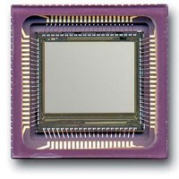
CYII5SC1300-EVAL Cypress Semiconductor Corp, CYII5SC1300-EVAL Datasheet - Page 11

CYII5SC1300-EVAL
Manufacturer Part Number
CYII5SC1300-EVAL
Description
BOARD EVAL IMG SENS IBIS5-B-1300
Manufacturer
Cypress Semiconductor Corp
Specifications of CYII5SC1300-EVAL
Sensor Type
CMOS Imaging, Color (RGB)
Sensing Range
1.3 Megapixel
Interface
Parallel/Serial
Sensitivity
106 fps
Voltage - Supply
3 V ~ 4.5 V
Embedded
No
Utilized Ic / Part
IBIS5-B-1300
Lead Free Status / RoHS Status
Contains lead / RoHS non-compliant
Lead Free Status / RoHS Status
Lead free / RoHS Compliant, Contains lead / RoHS non-compliant
Document #: 38-05710 Rev. *A
Snapshot (Synchronous) Shutter
A synchronous (global, snapshot) shutter solves the inconve-
nience found in the rolling shutter. Light integration takes place
on all pixels in parallel, although subsequent readout is
sequential.
Figure 14
synchronous shutter. All pixels are light sensitive at the same
period of time. The whole pixel core is reset simultaneously
and after the integration time all pixel values are sampled
together on the storage node inside each pixel. The pixel core
is read out line by line after integration. Note that the
integration and read out cycle is carry-out in serial, which
causes that no integration is possible during read out.
During synchronous shutter the input pins SS_START and
SS_STOP are used to start and stop the synchronous shutter.
Sequencer
Figure 5 on page 4
needed to operate the sensor in a particular sub-sampling
mode with a certain integration time, output amplifier gain, etc.
shows the integration and read out sequence for the
shows a number of control signals that are
Line number
Integration time
Figure 14. Synchronous Shutter Operation
Most of these signals are generated on-chip by the sequencer
that uses only a few control signals. These control signals
should be generated by the external system:
The relative position of the pulses is determined by a number
of data bits that are uploaded in internal registers through the
serial or parallel interface.
Internal Registers
Table 10 on page 12
a short description. In the next section, the registers are
explained in more detail.
• SYS_CLOCK (X-clock), which defines the pixel rate
• Y_START pulse, which indicates the start of a new frame
• Y_CLOCK, which selects a new row and starts the row
• SS_START and SS_STOP to control the integration period
read out
blanking sequence, including the synchronization and
loading of the X-register
in snapshot shutter mode.
Burst Readout time
shows a list of the internal registers with
Time axis
CYII5FM1300AB
IBIS5-B-1300
Page 11 of 42
[+] Feedback


