HW-SD1800A-DSP-SB-UNI-G Xilinx Inc, HW-SD1800A-DSP-SB-UNI-G Datasheet
HW-SD1800A-DSP-SB-UNI-G
Specifications of HW-SD1800A-DSP-SB-UNI-G
HW-SD1800A-DSP-DB-UNI-G
HW-SD1800A-DSP-DB-UNI-G
HW-SD1800A-DSP-SB-UNI-G
Available stocks


Related parts for HW-SD1800A-DSP-SB-UNI-G


HW-SD1800A-DSP-SB-UNI-G Summary of contents
Page 1
Spartan-3A DSP Starter Platform User Guide UG454 (v1.1) January 30, 2009 R ...
Page 2
Xilinx, Inc. All Rights Reserved. XILINX, the Xilinx logo, and other designated brands included herein are trademarks of Xilinx, Inc. All other trademarks are the property of their respective owners. NOTICE OF DISCLAIMER: Xilinx is providing this design, ...
Page 3
Table of Contents Overview . . . . . . . . . . . . . . . . . . . . . . . . . . . . . . . . . . . . ...
Page 4
Spartan-3A DSP Starter Platform User Guide www.xilinx.com UG454 (v1.1) January 30, 2009 ...
Page 5
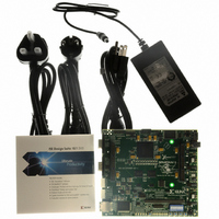
R Spartan-3A DSP 1800A Board Features Overview The purpose of this manual is to describe the functionality and contents of the Spartan®- 3A DSP Starter Platform from Xilinx. This document includes instructions for operating the board and descriptions of the ...
Page 6
... Eridon debug connector (SATA) Ordering Information Table 1 lists the evaluation kit part numbers. Table 1: Evaluation Kit and Hardware Ordering Information Part Number HW-SD1800A-DSP-SB-UNI-G XtremeDSP Starter Platform - Spartan-3A DSP 1800A 30 Hardware Edition www.xilinx.com Spartan-3A DSP Starter Platform User Guide R UG454 (v1.1) January 30, 2009 ...
Page 7
R Functional Description A high-level block diagram of the Spartan-3A DSP Starter Platform is shown in Subsequent sections provide details of the board design. X-Ref Target - Figure 1 Configuration and System ACE Connector Parallel Cable IV JTAG Port Debug/Comm ...
Page 8
Functional Description Xilinx Spartan-3A DSP FPGA The Xilinx XC3SD1800A-4FG676C device designed into the Spartan-3A DSP Starter Platform provides four I/O banks — two are fixed voltage and two are I/O voltage- selectable. The four I/O banks are described in provided ...
Page 9
R Table 2: XC3SD1800A Input and Output Allocation (Cont’d) I/O Bank Number 3 3 Note: 1. FLASH_DO and SPI_MISO are a common pin. Memory The Spartan-3A DSP Starter Platform is populated with both high-speed RAM (128Mbytes DDR2) and non-volatile ROM ...
Page 10
Functional Description Figure 3 shows terminator locations relative to the FPGA and the DDR2 memory devices. X-Ref Target - Figure 3 Spartan 3A DSP FPGA The following guidelines were used in the design of the DDR2 interface to the Spartan-3A ...
Page 11
R • 60-ohm pull-up resistor to the termination supply at the split-point of shared signals (control, address) • Termination supply that can both source and sink current • Feedback clock routed with twice the length to simulate the total flight ...
Page 12
Functional Description Table 3: FPGA DDR2 Interface Pinout (Cont’d) DDR2 Signal FPGA_DDR_CLK_0 FPGA_DDR_CLK_0# FPGA_DDR_CLK_1 FPGA_DDR_CLK_1# MB_FB_CLK (out) MB_FB_CLK (in) RST_DQS_DIV (out) RST_DQS_DIV (in) FPGA_DDR_LDQS_0 FPGA_DDR_LDQS_#0 FPGA_DDR_LDQS_1 FPGA_DDR_LDQS_#_1 FPGA_DDR_UDQS_0 FPGA_DDR_UDQS_#0 FPGA_DDR_UDQS_1 FPGA_DDR_UDQS_#_1 Intel J3 Parallel Flash The Flash memory consists of ...
Page 13
R Table 4: Parallel Flash Interface Pinout J3 Flash Signal FLASH_A0 FLASH_A1 FLASH_A2 FLASH_A3 FLASH_A4 FLASH_A5 FLASH_A6 FLASH_A7 FLASH_A8 FLASH_A9 FLASH_A10 FLASH_A11 FLASH_A12 FLASH_A13 FLASH_A14 FLASH_A15 FLASH_A16 FLASH_A17 Intel S33 Serial Flash 64Mbits of serial flash memory is provided by ...
Page 14
Functional Description SystemACE Module (SAM) Connector The Spartan-3A DSP Starter Platform provides a SAM 50-pin connector (J8) for SystemACE interface that can be used to configure the Spartan-3A DSP FPGA, and provide storage for A/V media files from removable Compact ...
Page 15
R Table 6: SAM Interface Signals FPGA Pin Number AA23 AA25 AA22 Interfaces The Spartan-3A DSP FPGA has access to Ethernet and RS232 physical layer transceivers for communication purposes. Network access is provided by a 10/100/1000 Mb/s Ethernet PHY, which ...
Page 16
Functional Description Other interfaces consist of two 0.1” 6-pin headers to accept Digilent plug-in modules pin Serial ATA connector ( this is not a serial ATA interface) to connect to an Eridon debug module, and a 0.1” 2 ...
Page 17
R Table 7: Ethernet PHY Interface Signals Ethernet PHY Signal ETH_Tx_D ETH_Tx_D ETH_Tx_D ETH_Tx_D ETH_Tx_D ETH_Tx_D ETH_Tx_D ETH_Tx_D ETH_Tx_EN ETH_Tx_ER ETH_GTX_CLK ETH_MDC ETH_MDIO ETH_RST# ETH_CRS The PHY address is set to 0b00001 by default. PHY address 0b00000 is reserved for ...
Page 18
Functional Description Table 8: Ethernet PHY Hardware Strapping Options Function Auto Negotiation Full/Half Duplex* Speed 1* Speed 0* PHY address 0* Non-IEEE Compliant Mode Manual MDIX Setting Auto MDIX Setting Multiple Node Enable Clock to MAC Enable 42 Jumper Resistor ...
Page 19
R The auto-MDIX mode provides automatic swapping of the differential pairs. This allows the PHY to work with either a straight-through cable or crossover cable. Use a CAT-5e or CAT-6 Ethernet cable when operating at 1000 Mb/s (Gigabit Ethernet). The ...
Page 20
Functional Description For Digilent modules, see: http://www.digilentinc.com/Products/Catalog.cfm?Nav1=Products&Nav2=Peripheral &Cat=Peripheral. X-Ref Target - Figure 6 Table 11: Digilent Header Connections J6 Signal DIGI2_1 DIGI2_2 DIGI2_3 DIGI2_4 Debug Connector (This is not a Serial ATA Connector) A Serial ATA connector (J3) provides a ...
Page 21
R Table 12: Debug Connector (J3) J3 Pin Number VGA Output The Spartan-3A DSP Starter Platform includes a VGA video output using a resistor-divider network and 4-bits per RGB color as shown in 510, 1K, 2K, & 4K ohms for ...
Page 22
Functional Description Table 13: VGA Pin Assignments VGA Signal DAC_B2 DAC_B3 Miscellaneous I/O An 8-position DIP switch, 4 user Pushbuttons, and 8 user LEDs are provided on the Spartan-3A DSP Starter Platform. The connection of these devices to the FPGA ...
Page 23
R Expansion Connectors The Spartan-3A DSP Starter Platform provides expansion capabilities for customized user application daughter cards and interfaces over two EXP expansion connectors. The EXP expansion connectors on the board can support two half-card EXP modules or a single ...
Page 24
Functional Description specification can serve a dual role. All the differential I/O signals can be configured as either differential pairs or single-ended signals, as required by the end application. In providing differential signaling, higher performance LVDS interfaces can be implemented ...
Page 25
R Table 16: EXP Connector JX1 Pinout (Cont’d) FPGA Pin No. B19 A19 - C18 B18 - A18 C17 B14 A14 - D17 B17 D16 C15 - D13 C12 - A12 B12 - C11 D11 C10 D10 ...
Page 26
Functional Description Table 16: EXP Connector JX1 Pinout (Cont’d) FPGA Pin No. B13 C13 Table 17: EXP Connector JX2 Pinout FPGA Pin No. V16 Y17 - ...
Page 27
R Table 17: EXP Connector JX2 Pinout (Cont’d) FPGA Pin No. W15 AB16 - M21 AC16 - U22 AC15 AA13 Y13 - V14 U15 - V10 W10 - V13 W13 - Y12 AA12 - W17 V17 - V12 W12 AD11 ...
Page 28
Configuration Table 17: EXP Connector JX2 Pinout (Cont’d) FPGA Pin No. AE14 - AB9 AC9 - Y10 AA10 - V11 U11 - AF5 AE6 Configuration The Spartan-3A DSP Starter Platform provides four mechanisms to program and configure ...
Page 29
R X-Ref Target - Figure 9 Configuration Modes The following table shows the Spartan-3A DSP configuration modes set by Jumper JP9. All mode jumpers (including the PUDC_B pin) are pulled up; jumper installation grounds the connection. configuration settings at JP9. ...
Page 30
Board Power Table 18: FPGA Configuration Mode Jumper (JP9) Settings Mode Master Serial Master Serial Slave Serial Slave Serial Master SPI Master SPI BPI Up BPI Up Slave Parallel Slave Parallel JTAG JTAG X-Ref Target - Figure 10 Board Power ...
Page 31
R consequently, PI filters on the output of each of the PTH05050WAZ and PTH04000WAZ are utilized to minimize these transients. X-Ref Target - Figure 11 Based on measurements during prototyping, the PTH04000 circuit for 1.2V was tuned to increase the ...
Page 32
Board Clocks Proper decoupling of the various FPGA power rails is extremely important; this design adheres to Xilinx application note XAPP623 http://direct.xilinx.com/bvdocs/appnotes/xapp623.pdf. The decoupling strategy on the Spartan-3A DSP Starter Platform is shown in Table 19: FPGA Decoupling Capacitors Total ...
Page 33
R Table 20: Clock Sources Clock Source 125 MHz oscillator (U7) 25.175 MHz oscillator (U4) Socket SMA connector J1 The SMA connector is AC-terminated through a 0.1uF 0402 capacitor. Between J1 and the capacitor is a 0-ohm 0402 resistor. Between ...
Page 34
Related Resources www.em.avnet.com/exp www.em.avnet.com/systemace www.em.avnet.com/aes Texas Instruments www.ti.com www.ti.com/power www.ti.com/xilinx Regulators focus.ti.com/docs/prod/folders/print/pth04000w.html focus.ti.com/docs/prod/folders/print/pth05050w.html focus.ti.com/docs/prod/folders/print/tps51116.html Supervisors focus.ti.com/docs/prod/folders/print/tps3828-50.html focus.ti.com/docs/prod/folders/print/tps3808g01.html focus.ti.com/docs/prod/folders/print/tps3307-25.html RS232 focus.ti.com/docs/prod/folders/print/max3221e.html Intel www.intel.com www.intel.com/design/flcomp/prodbref/s33.htm?iid=ipp_embed+flash_s33& www.intel.com/design/flcomp/prodbref/308275.htm?iid=ipp_embed+flash_j3d& Fox www.foxonline.com/ www.foxonline.com/xpresso_xo.htm www.foxonline.com/smd_xtals.htm www.foxonline.com/thruhole_osc.htm National Semiconductor www.national.com www.national.com/pf/DP/DP83865.html 58 www.xilinx.com Spartan-3A DSP Starter Platform User ...
Page 35
R Samtec www.samtec.com/ www.samtec.com/technical_specifications/overview.aspx?series=QTE Tyco/Amp www.tycoelectronics.com/ http://catalog.tycoelectronics.com/TE/bin/TE.Connect?C=1&M=BYPN&PID=407634& PN=1-6605833-1&I=13 Spartan-3A DSP Starter Platform User Guide UG454 (v1.1) January 30, 2009 www.xilinx.com Related Resources 59 ...
Page 36
Related Resources 60 www.xilinx.com Spartan-3A DSP Starter Platform User Guide R UG454 (v1.1) January 30, 2009 ...
Page 37
R Connector, Header, and Jumper Locations Figure A-1 X-Ref Target - Figure A JX1 JP6 JT1 through JT7, inclusive Figure A-1: Connector, Header, and Jumper Locations Spartan-3A DSP Starter Platform UG454 (v1.1) January ...
Page 38
Spartan-3A DSP Starter Platform R UG454 (v1.1) January 30, 2009 ...