AT91SAM9M10-G45-EK Atmel, AT91SAM9M10-G45-EK Datasheet
AT91SAM9M10-G45-EK
Specifications of AT91SAM9M10-G45-EK
Available stocks


Related parts for AT91SAM9M10-G45-EK


AT91SAM9M10-G45-EK Summary of contents
Page 1
... AT91SAM9M10-G45-EK .................................................................................................................... User Guide 6495B–ATARM–21-Apr-10 ...
Page 2
... TV-Out Extension .............................................................................................. 4-17 4.2.9 Software Controlled LEDs ................................................................................. 4-18 4.2.10 Serial Peripheral Interface Controller (SPI) ....................................................... 4-19 4.2.11 Two Wire Interface (TWI)................................................................................... 4-19 4.2.12 SD/MMC Interface ............................................................................................. 4-19 4.2.13 TFT LCD with Touch Panel ............................................................................... 4-20 4.2.14 Push Buttons ..................................................................................................... 4-22 AT91SAM9M10-G45-EK User Guide 1-i 6495B–ATARM–21-Apr-10 ...
Page 3
... Image Sensor - ISI ............................................................................................................. 6-9 6.12 Video ................................................................................................................................ 6-10 6.13 Display Devices................................................................................................................ 6-10 6.13.1 TFT LCD ............................................................................................................ 6-10 6.14 LCD Extension ................................................................................................................. 6-11 Section 7 Schematics .................................................................................................................7-1 7.1 Schematics......................................................................................................................... 7-1 Section 8 Revision History..........................................................................................................8-1 8.1 Revision History ................................................................................................................. 8-1 1-ii 6495B–ATARM–21-Apr-10 AT91SAM9M10-G45-EK User Guide ...
Page 4
... The SAM9M10-G45-EK includes many hardware peripherals such as: Two high speed USB hosts and one high speed device port An Ethernet 10/100 interface Two high speed multimedia card interfaces AT91SAM9M10-G45-EK User Guide Section 1 Introduction 1-1 6495B–ATARM–21-Apr-10 ...
Page 5
... Title This document describes the SAM9G45, which is part of the ® Atmel's Smart ARM It is available from http://www.atmel.com/dyn/resources/prod_documents/doc6438.pdf This document describes the SAM9M10, which is part of the ® Atmel's Smart ARM http://www.atmel.com/dyn/resources/prod_documents/doc6355.pdf Comments Microcontrollers. Microcontrollers AT91SAM9M10-G45-EK User Guide ...
Page 6
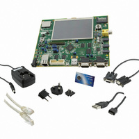
... One RJ45 crossed cable A Welcome Letter Figure 2-1. Unpacked SAM9M10-G45-EK Unpack and inspect this kit carefully. Contact your local Atmel distributor, should you have issues con- cerning the contents of the kit. AT91SAM9M10-G45-EK User Guide Section 2 Kit Contents 2-1 6495B–ATARM–21-Apr-10 ...
Page 7
... Avoid touching the component pins or any other metallic element on the board. 2-2 6495B–ATARM–21-Apr-10 Specifications 400 MHz PCK, 133 MHz MCK Ethernet, USB, RS232, DBGU, JTAG 5 VDC from connector -10° to +50° C -40° to +85° 90% (non condensing) 180 mm x 140 mm Compliant AT91SAM9M10-G45-EK User Guide ...
Page 8
... SAM9M10-G45-EK. Optionally, if you have a SAM-ICE™, instructions are also given about how to debug the code. We recommend that you backup the “SAM9M10-G45-EK DevStart” folder on your computer before launching it. AT91SAM9M10-G45-EK User Guide Section 3 Power up 3-1 6495B–ATARM–21-Apr-10 ...
Page 9
... Follow the instructions if you deleted the contents of the NAND Flash and want to recover from this situation. 3.5 Sample Code and Technical Support After boot up, you can run some sample code or your own application on the development kit. You can http://www.atmel.com/dyn/products/tech_support.asp?Faq=y&family_id=689%20. 3-2 6495B–ATARM–21-Apr- AT91SAM9M10-G45-EK User Guide ...
Page 10
... The board is equipped with an AT91SAM9M10-CU embedded microprocessor (324-ball TFBGA pack- age) together with the following interfaces or peripherals: DDR2/LPDDR memory interface is connected to 128 MB DDR2-SDRAM memory External Bus Interface (EBI) is connected to three kinds of memory devices (DDR2-SDRAM, NAND Flash and NOR Flash (not populated)) AT91SAM9M10-G45-EK User Guide Multimedia cards Data PARALLEL Flash ...
Page 11
... Main power supply (J2) 4.1.3 Push Button Switches Reset, board reset (BP1) Wake up, push button to bring processor out of low power mode (BP2) Right and left click, user push button switches (BP4 and BP5) Joystick (BP3) 4-2 6495B–ATARM–21-Apr-10 AT91SAM9M10-G45-EK User Guide ...
Page 12
... The board features the Atmel SAM9M10-CU 324-ball TFBGA package. This chip runs at a nominal fre- quency of 400 MHz for the core and 133 MHz for the system bus. For more information, refer to the latest SAM9M10 datasheet available from AT91SAM9M10-G45-EK User Guide HOST DEVICE ...
Page 13
... Crystal for RTC Clock, 32.768 kHz Oscillator for Ethernet Clock RMII, 50 MHz Crystal for Ethernet Clock MII, 25 MHz (not populated) Crystal for AC97 Codec Clock, 24.576 MHz Crystal for TV Encoder Clock, 13 MHz, or Oscillator for TV Encoder, 13 MHz (not populated) Component assignment AT91SAM9M10-G45-EK User Guide ...
Page 14
... Figure 4-3. EBI0 - DDR2 AT91SAM9M10-G45-EK User Guide Board Description 4-5 6495B–ATARM–21-Apr-10 ...
Page 15
... Board Description Figure 4-4. EBI1 - DDR2 + Flash 4-6 6495B–ATARM–21-Apr-10 AT91SAM9M10-G45-EK User Guide ...
Page 16
... The 1.0 VDC Core Supply (VDDUTMIC, VDDPLLUTMI and VDDPLLA) is generated by an adjustable LDO RT9186A series powered by the output of the 3.3 VDC Supply. Note: 1. Corresponding test points (TP1 to TP4, GND) are used with jumpers (JP1.1 to JP7) to AT91SAM9M10-G45-EK User Guide 1 are distributed as necessary to each part of the circuit permit probing of these voltages ...
Page 17
... C20 C20 4.7u 4. 10uH 10uH VDDPLLA R20 R20 1R 1R C28 C28 100n 100n C29 C29 4.7u 4.7u 1V J1-3 J1 VDDCORE 1V8 JP5 JP5 1 3 JP6 JP6 VDDIOM0 1 3 VDDIOM1 J3 J3 3V3 JP7 JP7 1 3 C30 C30 100n 100n VDDBU AT91SAM9M10-G45-EK User Guide ...
Page 18
... Figure 4-6. Management Power Block REGULATED 5V ONLY POWER JACK DC POWER JACK Q1 Q1 Si1563EDH Si1563EDH JP4 JP4 SIP2 SIP2 FORCE POWER ON SHDN AT91SAM9M10-G45-EK User Guide 3V3 R3 R3 100k 100k CR1 CR1 + 3 33u 33u C10 C10 1u 1u 10u 10u 5V PWR_EN R9 R9 100k 100k ...
Page 19
... NTRST NTRST TDI TDI TMS TMS TCK TCK 0R 0R RTCK RTCK TDO TDO NRST NRST 1 C159 C159 100n 100n 3V3 3 4 C163 C163 100n 100n R87 R87 R88 R88 100k 100k 100k 100k R90 R90 AT91SAM9M10-G45-EK User Guide PB13 PB12 ...
Page 20
... USB Host Port0 is directly connected to the first UTMI transceiver. The second Host Port (Port1) is mul- tiplexed with the USB Device High speed and connected to the second UTMI port. One USB high/full speed type standard A connector One USB interface Host/Device Micro AB connector Refer to the SAM9M10 datasheet for detailed programming information. AT91SAM9M10-G45-EK User Guide MN16 MN16 1 16 ...
Page 21
... USB HOST/DEVICE INTERFACE ® Standard 802.3. MN17 MN17 (ENA OUTA ENA (FLGA FLGA (FLGB GNG FLGB (ENB OUTB ENB AIC1526-0GS AIC1526-0GS 3V3 R97 R97 47k 47k (IDUSB) AT91SAM9M10-G45-EK User Guide HDMA HDPA PD1 PD2 PD4 PD3 HDMB HDPB PD28 ...
Page 22
... ECOL: collision detect ECRS: carrier sense / ECRS data valid EMDC EMDC: management data clock EMDIO: management data EMDIO input / output NRST NRST: microcontroller reset AT91SAM9M10-G45-EK User Guide Normal MII Mode DM9161 TXD [0:1] TXD [2:3] TXEN TXER/TXD[4] TXCLK RXD [0:1] RXD [2:3] RXER/RXD[4]/ ...
Page 23
... Board Description Figure 4-11. Ethernet Port For more information about the Ethernet controller device, refer to the Davicom DM9161 controller man- ufacturer's datasheet. 4-14 6495B–ATARM–21-Apr- AT91SAM9M10-G45-EK User Guide ...
Page 24
... The SAM9M10-G45-EK includes a WM9711L AC97 CODEC for digital sound input and output. This interface includes audio jacks for MIC input (J9), line audio input (J8), headphone line output (J7) and a 2-point speaker output connector (JP15 compliant with AC97 Component Specification V2.2. AT91SAM9M10-G45-EK User Guide Board Description 4-15 6495B–ATARM–21-Apr-10 ...
Page 25
... R83 R83 R84 R84 AGND_AC97 680R 680R 680R 680R L10 L10 220ohm at 100MHz 220ohm at 100MHz L12 L12 220ohm at 100MHz 220ohm at 100MHz C155 C155 470p 470p AGND_AC97 AT91SAM9M10-G45-EK User Guide HEADPHONE LINE-OUT C129 C129 3 4 470p 470p STEREO_3.5mm STEREO_3.5mm LINE- C149 C149 ...
Page 26
... DNP DNP VDD VDD E E 13MHz 13MHz 2 3 VSS VSS OUT OUT DNP DNP C207 C207 100n 100n DNP DNP AT91SAM9M10-G45-EK User Guide MN20 MN20 CH7024B CH7024B PE23 VDDIO PE24 DVDD PE25 44 D2 PE26 45 D3 PE27 46 D4 PE28 47 D5 PE29 ...
Page 27
... BP3 BP3 PB14 LEFT RIGHT 2 5 PB18 PUSH DOWN 3 6 JOYSTICK PB17 C32 C32 C33 C33 C34 C34 C35 C35 10n 10n 10n 10n 10n 10n R28 R28 100R 100R AT91SAM9M10-G45-EK User Guide PD0 PD31 C36 C36 10n 10n 10n 10n ...
Page 28
... SD/MMC card slot. The second interface is used as a 4-bit interface (MCI0), connected to a 4-bit SD/MMC card slot. The users must provide their own compatible cards for use with these connectors. Please note that the power is connected to VCC, which is 3.3 volts. AT91SAM9M10-G45-EK User Guide ® . 3V3 ...
Page 29
... PA4 (MCI0_DA2 RR40 RR40 27R 27R SD/MMC CARD INTERFACE - MCI0 3V3 R197 R197 R198 R198 RR36 RR36 10k 10k 68k 68k 68k 68k 3V3 C123 C123 100n 100n R65 R65 10k 10k C122 100n C122 100n 6 3V3 AT91SAM9M10-G45-EK User Guide ...
Page 30
... VLED COMP R123 R123 R137 R137 C203 C203 10K 10K 10R 10R 220nF 220nF 20mA MAX 9 LEDs Back Light AT91SAM9M10-G45-EK User Guide 3V3 pin45 pin44 pin43 VLED+ pin42 VLED- pin41 pin40 YpLCD pin39 XpLCD R180 R180 pin38 YmLCD 10K 10K pin37 ...
Page 31
... BP1 BP1 NRST BP2 BP2 WAKE UP BP4 BP4 RIGHT CLICK C31 C31 R27 R27 100R 100R 10n 10n BP5 BP5 LEFT CLICK C37 C37 R29 R29 10n 10n 100R 100R R24 R24 1k 1k NRST WAKE UP PB7 PB6 AT91SAM9M10-G45-EK User Guide ...
Page 32
... Figure 4-21. Expansion Slot AT91SAM9M10-G45-EK User Guide CONNECTOR EXTENSION FOR LARGE LCD J23 J23 DNP DNP PE8 1 2 PE10 3 4 PE12 5 6 PE14 7 8 PE16 9 10 PE18 11 12 PE20 13 14 PE22 15 16 PE24 17 18 PE26 19 20 PE28 21 22 PE30 LCDHSYNC 27 28 ...
Page 33
... RMII is the factory default mode. To evaluate the MII mode, the user has to unsolder R99 and solder R100, R103 to R105, R108 to R110, R112, R114, C174, C175, Y5. AT91SAM9M10-G45-EK User Guide Feature Disables the ICE NTRST input Enables the ICE RTCK return. R94 must be opened Enables the ICE NRST input Disables TCK < ...
Page 34
... External power to VDDIOM1 1-2 VDDBU JP7 2-3 VDDBU JP11.1: SO JP14.1 = Line_Out Feature 3V3 nominal 3V3 nominal 3V3 nominal 1V8 nominal 1V8 nominal Lithium 3V Battery 3.3V from regulator JP11.2: SI JP11.3: SCK JP14.3 = AGND AT91SAM9M10-G45-EK User Guide 3V3 3V3 3V3 3V3 1V8 1V8 ...
Page 35
... The multiplexing tables in the following paragraphs define how the I/O lines of peripherals A and B are multiplexed on the PIO Controllers. 5.5.2 Multiplexing on PIO Controller A (PIOA) "R.Select" = connection selectable via an on-board resistor (default not populated) AT91SAM9M10-G45-EK User Guide Default Setting N.P JTAGSEL ...
Page 36
... VDDIOP0 VDDIOP0 VDDIOP0 VDDIOP0 VDDIOP0 VDDIOP0 VDDIOP0 VDDIOP0 VDDIOP0 VDDIOP0 VDDIOP0 VDDIOP0 VDDIOP0 VDDIOP0 VDDIOP0 VDDIOP0 VDDIOP0 VDDIOP0 VDDIOP0 VDDIOP0 VDDIOP0 VDDIOP0 VDDIOP0 VDDIOP0 VDDIOP0 Ethernet MII VDDIOP0 Ethernet MII VDDIOP0 Ethernet MII VDDIOP0 Ethernet MII VDDIOP0 VDDIOP0 AT91SAM9M10-G45-EK User Guide ...
Page 37
... ISI_PCK PB29 ISI_VSYNC PB30 ISI_HSYNC PB31 ISI_MCK PCK1 AT91SAM9M10-G45-EK User Guide Function and Comments SPI Slave Out Serial DataFlash SPI Slave In Serial DataFlash SPI Serial Clock Serial DataFlash SPI Chip Select Serial DataFlash USART1 Transmit Data USART1 Receive Data User Push Button Right click ...
Page 38
... PC31 D31 5-6 6495B–ATARM–21-Apr-10 Function and Comments Add19 NAND Flash Add20 NAND Flash ALE NAND Flash CLE NAND Flash Ready/Busy NAND Flash Chip select NAND Flash AT91SAM9M10-G45-EK User Guide Power VDDIOM1 VDDIOM1 VDDIOM1 VDDIOM1 VDDIOM1 VDDIOM1 VDDIOM1 VDDIOM1 VDDIOM1 ...
Page 39
... PD29 TCLK1 SCK1 PD30 TIOB0 SCK2 PD31 TIOB1 PWM1 AT91SAM9M10-G45-EK User Guide PWM3 Command LED2 Output ENA USB Host Input FLGA USB Host Output ENB USB Host Input FLGB USB Host Int. Ethernet 10/100 MDINTR AC97 Receive Signal AC97 Transmit Signal ...
Page 40
... LCD-Red7 LCD-Green0 LCD-Green1 LCD-Green2 LCD-Green3 LCD-Green4 LCD-Green5 LCD-Green6 LCD-Green7 LCD-Blue0 LCD-Blue1 LCD-Blue2 LCD-Blue3 LCD-Blue4 LCD-Blue5 LCD-Blue6 LCD-Blue7 AC97 External Clock AT91SAM9M10-G45-EK User Guide Power VDDIOP1 VDDIOP1 VDDIOP1 VDDIOP1 VDDIOP1 VDDIOP1 VDDIOP1 VDDIOP1 VDDIOP1 VDDIOP1 VDDIOP1 VDDIOP1 VDDIOP1 VDDIOP1 VDDIOP1 VDDIOP1 VDDIOP1 ...
Page 41
... Table 6-1. Power Supply Connector J2 Signal Description Pin 1 2 6.2 RS232 Connector with RTS/CTS Handshake Support Connector J11 is the COM1 connector. Figure 6-2. RS232 COM1 Connector J11 AT91SAM9M10-G45-EK User Guide Figure 6-1. The positive pole must center pin. Mnemonic Signal description Center +5 VCC Gnd Section 6 ...
Page 42
... RTS READY TO SEND Active-positive RS232 input signal CTS CLEAR TO SEND Active-positive RS232 output signal Mnemonic NC NO CONNECTION TXD TRANSMITTED DATA RS232 serial data output signal RXD RECEIVED DATA RS232 serial data input signal GND GROUND Signal description Signal description AT91SAM9M10-G45-EK User Guide ...
Page 43
... Figure 6-5. USB Host type A connector J12 Table 6-5. USB Host Type A Connector J12 Signal Descriptions Pin Mnemonic 1 Vbus Gnd 5 Shield AT91SAM9M10-G45-EK User Guide Mnemonic Pin Signal description 5v power Data minus Data plus Ground Shield Connectors Mnemonic Txdata- DIFFERENTIAL OUTPUT MINUS ...
Page 44
... A SAM-ICE connector is a 20-way Insulation Displacement Connector (IDC) keyed box header (2.54 mm male) that mates with IDC sockets mounted on a ribbon cable. Figure 6-7. JTAG/ICE Connector J13 6-4 6495B–ATARM–21-Apr-10 Signal description 5v power Data minus Data plus On the Go Identification Ground AT91SAM9M10-G45-EK User Guide ...
Page 45
... GND 19 RFU 20 GND AT91SAM9M10-G45-EK User Guide Description This is the target reference voltage used to check if the target has power, to create the logic-level reference for the input comparators, and to control the output logic levels to the target normally fed from VDD on the target board and must not have a series resistor ...
Page 46
... SD/MMC- MCI0 Connector J6 is the SD/MMC connector. Figure 6-8. SD/MMC0 Connector J6 Table 6-8. SD/MMC0 Connector J6 Signal Descriptions Pin Mnemonic 1 RSV/DAT3 3 GND 5 7 DAT0 9 DAT2 11 GND 6-6 6495B–ATARM–21-Apr-10 Pin Mnemonic 2 CDA 4 VCC CLK 6 GND 8 DAT1 10 Card Detect 12 AT91SAM9M10-G45-EK User Guide ...
Page 47
... Connector J5 is the SD/MMC connector. Figure 6-9. SD/MMC1 Connector J5 Table 6-9. SD/MMC1 Connector J5 Signal Descriptions Pin Mnemonic 1 RSV/DAT3 3 GND 5 7 DAT0 9 DAT2 11 DAT4 13 DAT6 AT91SAM9M10-G45-EK User Guide Pin Mnemonic 2 CMD 4 VCC CLK 6 8 DAT1 10 DAT3 12 DAT5 14 DAT7 Connectors 6-7 6495B–ATARM–21-Apr-10 ...
Page 48
... Connector JP15 is the Speaker Output connector Figure 6-10. Audio Connector J7, J8, J9 Table 6-10. J7, J8, J9 Signal Description Pin Table 6-11. Speaker JP15 Signal Descriptions Pin 1 2 6-8 6495B–ATARM–21-Apr-10 Mnemonic Signal Signal Gnd Mnemonic Speaker bridge output A Speaker bridge output B AT91SAM9M10-G45-EK User Guide ...
Page 49
... Figure 6-11. ISI Connector J17 Table 6-12. ISI Connector J17 Signal Descriptions Pin Mnemonic 1 VCC 3v3 3 VCC 3v3 ISI_Data1 21 ISI_Data3 23 ISI_Data5 25 ISI_Data7 27 ISI_Data9 29 ISI_Data11 AT91SAM9M10-G45-EK User Guide Pin Mnemonic 2 Gnd 4 Gnd Ctrl1 6 Ctrl2 SCL 8 SDA Gnd 10 ISI_MCK Gnd 12 ISI_VSYNC Gnd 14 ISI_HSYNC Gnd 16 ISI_PCK Gnd 18 ...
Page 50
... Connector J24 is the TFT-LCD connector. Figure 6-13. TFT LCD Connector J24 Table 6-14. TFT LCD Connector J24 Signal Descriptions Pin 6-10 6495B–ATARM–21-Apr-10 Mnemonic Signal description Center Composite video signal output Mnemonic Pin VLED- 2 GND Mnemonic VLED+ VDD 3V3 AT91SAM9M10-G45-EK User Guide ...
Page 51
... Connectors J23 and J18 are for an optional LCD extension (not populated). Table 6-15. Connector J23 Signal Description for an LCD Extension Pin 1 3 PE10 5 PE12 7 PE14 9 PE16 11 PE18 13 PE20 15 PE22 17 PE24 19 PE26 21 PE28 23 PE30 AT91SAM9M10-G45-EK User Guide Mnemonic Pin GND 30 DISPON 32 VSYNC 34 NO CONNECT 36 ...
Page 52
... GND (0V) VCC +3V3 power source Pin Mnemonic 32 PE2 LCDCC 34 PE1 LCDMOD 36 PD15 GPIO2 38 GND (0V Pin Mnemonic 2 XP AD0XP 4 YP AD2YP 6 GND (0V) 8 PD24 PD24 10 PD26 PD26 12 PD18 PD18 14 GND (0V) 16 +5V 18 GND (0V) 20 VCC +3V3 power source AT91SAM9M10-G45-EK User Guide ...
Page 53
... Top Level view, block architecture of the design Power Supply SAM Processor Bus impedance adaptor Main memory EBI memory MCI & TWI Audio AC97 Serial interfaces Ethernet LCD Video interfaces and LCD extension AT91SAM9M10-G45-EK User Guide Section 7 Schematics 7-1 6495B–ATARM–21-Apr-10 ...
Page 54
... R4 PE27 B4 IDUSB PE12 R5 PE28 B5 (MCI1_WP) PE13 R6 PE29 B6 AT91SAM9M10-G45-EK AT91SAM9M10-G45-EK AT91SAM9M10-G45-EK POWER_LED PE14 R7 PE30 B7 USER LED D7 PE15 G0 PE31 EXT_CLK TOP LEVEL TOP LEVEL TOP LEVEL This agreement is our property. Reproduction and publication without our written authorization shall expose offender to legal proceedings. This agreement is our property. Reproduction and publication without our written authorization shall expose offender to legal proceedings. ...
Page 55
... TP4 TP4 PB6 {3} AT91SAM9M10-G45-EK AT91SAM9M10-G45-EK AT91SAM9M10-G45-EK POW ER SUPPLY POW ER SUPPLY POW ER SUPPLY This agreement is our property. Reproduction and publication without our written authorization shall expose offender to legal proceedings. This agreement is our property. Reproduction and publication without our written authorization shall expose offender to legal proceedings. ...
Page 56
... NCS0 SIP2 SIP2 AT91SAM9M10-G45-EK AT91SAM9M10-G45-EK AT91SAM9M10-G45-EK AT91SAM9M10 chip AT91SAM9M10 chip AT91SAM9M10 chip This agreement is our property. Reproduction and publication without our written authorization shall expose offender to legal proceedings. This agreement is our property. Reproduction and publication without our written authorization shall expose offender to legal proceedings. ...
Page 57
... RR32D RR32D 5 AT91SAM9M10-G45-EK AT91SAM9M10-G45-EK AT91SAM9M10-G45-EK RES.ARRAYS-EBI0_EBI1 RES.ARRAYS-EBI0_EBI1 RES.ARRAYS-EBI0_EBI1 This agreement is our property. Reproduction and publication without our written authorization shall expose offender to legal proceedings. This agreement is our property. Reproduction and publication without our written authorization shall expose offender to legal proceedings. This agreement is our property. Reproduction and publication without our written authorization shall expose offender to legal proceedings. ...
Page 58
... E7 VSSDL DDR_VREF {3,6} AT91SAM9M10-G45-EK AT91SAM9M10-G45-EK AT91SAM9M10-G45-EK EBI0_DDR2 EBI0_DDR2 EBI0_DDR2 This agreement is our property. Reproduction and publication without our written authorization shall expose offender to legal proceedings. This agreement is our property. Reproduction and publication without our written authorization shall expose offender to legal proceedings. ...
Page 59
... AT91SAM9M10-G45-EK AT91SAM9M10-G45-EK AT91SAM9M10-G45-EK EBI1_MEMORY EBI1_MEMORY EBI1_MEMORY This agreement is our property. Reproduction and publication without our written authorization shall expose offender to legal proceedings. This agreement is our property. Reproduction and publication without our written authorization shall expose offender to legal proceedings. This agreement is our property. Reproduction and publication without our written authorization shall expose offender to legal proceedings. ...
Page 60
... DNP DNP AT91SAM9M10-G45-EK AT91SAM9M10-G45-EK AT91SAM9M10-G45-EK MCI & MCI & MCI & This agreement is our property. Reproduction and publication without our written authorization shall expose offender to legal proceedings. This agreement is our property. Reproduction and publication without our written authorization shall expose offender to legal proceedings. ...
Page 61
... AGND_AC97 AT91SAM9M10-G45-EK AT91SAM9M10-G45-EK AT91SAM9M10-G45-EK AUDIO AC97 AUDIO AC97 AUDIO AC97 This agreement is our property. Reproduction and publication without our written authorization shall expose offender to legal proceedings. This agreement is our property. Reproduction and publication without our written authorization shall expose offender to legal proceedings. ...
Page 62
... DNP DNP ICE INTERFACE AT91SAM9M10-G45-EK AT91SAM9M10-G45-EK AT91SAM9M10-G45-EK SERIAL INTERFACES SERIAL INTERFACES SERIAL INTERFACES This agreement is our property. Reproduction and publication without our written authorization shall expose offender to legal proceedings. This agreement is our property. Reproduction and publication without our written authorization shall expose offender to legal proceedings. ...
Page 63
... LINK&ACT AT91SAM9M10-G45-EK AT91SAM9M10-G45-EK AT91SAM9M10-G45-EK RMII_MII ETHERNET RMII_MII ETHERNET RMII_MII ETHERNET This agreement is our property. Reproduction and publication without our written authorization shall expose offender to legal proceedings. This agreement is our property. Reproduction and publication without our written authorization shall expose offender to legal proceedings. ...
Page 64
... R174 0R 0R PE10 AT91SAM9M10-G45-EK AT91SAM9M10-G45-EK AT91SAM9M10-G45-EK DISPLAY DISPLAY DISPLAY This agreement is our property. Reproduction and publication without our written authorization shall expose offender to legal proceedings. This agreement is our property. Reproduction and publication without our written authorization shall expose offender to legal proceedings. ...
Page 65
... PB31 (ISI_MCK) AT91SAM9M10-G45-EK AT91SAM9M10-G45-EK AT91SAM9M10-G45-EK LCD & ISI & VIDEO INTERFACE LCD & ISI & VIDEO INTERFACE LCD & ISI & VIDEO INTERFACE This agreement is our property. Reproduction and publication without our written authorization shall expose offender to legal proceedings. This agreement is our property. Reproduction and publication without our written authorization shall expose offender to legal proceedings. ...
Page 66
... Most configuration tables (with LEDs, pins and connectors) updated - ‘LG/Philips’ reference removed Figure 4-4, ” EBI1 - DDR2 + Flash” New ”Schematics” 6495A First issue. AT91SAM9M10-G45-EK User Guide Revision History Section 7.1 and new Schematics in Section 8 Change Request Ref. 6990 ...
Page 67
... Disclaimer: The information in this document is provided in connection with Atmel products. No license, express or implied, by estoppel or otherwise, to any intellectual property right is granted by this document or in connection with the sale of Atmel products. EXCEPT AS SET FORTH IN ATMEL’S TERMS AND CONDI- TIONS OF SALE LOCATED ON ATMEL’S WEB SITE, ATMEL ASSUMES NO LIABILITY WHATSOEVER AND DISCLAIMS ANY EXPRESS, IMPLIED OR STATUTORY WARRANTY RELATING TO ITS PRODUCTS INCLUDING, BUT NOT LIMITED TO, THE IMPLIED WARRANTY OF MERCHANTABILITY, FITNESS FOR A PARTICULAR PURPOSE, OR NON-INFRINGEMENT ...