AT91SAM9M10-G45-EK Atmel, AT91SAM9M10-G45-EK Datasheet - Page 2
AT91SAM9M10-G45-EK
Manufacturer Part Number
AT91SAM9M10-G45-EK
Description
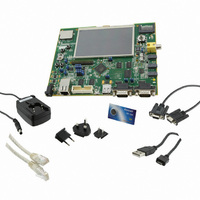
KIT EVAL FOR AT91SAMG45/9M10
Manufacturer
Atmel
Series
AT91SAM Smart ARMr
Type
MCUr
Specifications of AT91SAM9M10-G45-EK
Contents
Board, Cables, Power Supply
Processor To Be Evaluated
AT91SAM9M10
Processor Series
AT91SAM9
Data Bus Width
32 bit
Interface Type
RS-232, Ethernet, USB, JTAG
Operating Supply Voltage
5 V
Silicon Manufacturer
Atmel
Core Architecture
AVR
Kit Contents
Board
Features
Two High Speed USB Hosts, LCD TFT Display
Svhc
No SVHC (15-Dec-2010)
Mcu Supported Families
AT91SAM9M10,
Rohs Compliant
Yes
For Use With/related Products
AT91SAM9M10
Lead Free Status / RoHS Status
Lead free / RoHS Compliant
Available stocks
Company
Part Number
Manufacturer
Quantity
Price
Company:

Part Number:
AT91SAM9M10-G45-EK
Manufacturer:
INFINEON
Quantity:
10 000
Company:
Part Number:
AT91SAM9M10-G45-EK
Manufacturer:
Atmel
Quantity:
135


Section 1
Introduction .................................................................................................................1-1
Section 2
Kit Contents ................................................................................................................2-1
Section 3
Power up.....................................................................................................................3-1
Section 4
Board Description .......................................................................................................4-1
AT91SAM9M10-G45-EK User Guide
1.1
1.2
2.1
2.2
2.3
3.1
3.2
3.3
3.4
3.5
4.1
4.2
Scope ................................................................................................................................. 1-1
Applicable Documents ....................................................................................................... 1-2
Deliverables ....................................................................................................................... 2-1
Evaluation Board Specifications......................................................................................... 2-2
Electrostatic Warning ......................................................................................................... 2-2
Power Up the Board........................................................................................................... 3-1
Battery................................................................................................................................ 3-1
DevStart ............................................................................................................................. 3-1
Recovery Procedure .......................................................................................................... 3-2
Sample Code and Technical Support ................................................................................ 3-2
Equipment on the Board .................................................................................................... 4-1
Hardware Layout and Configuration .................................................................................. 4-3
4.1.1
4.1.2
4.1.3
4.1.4
4.2.1
4.2.2
4.2.3
4.2.4
4.2.5
4.2.6
4.2.7
4.2.8
4.2.9
4.2.10 Serial Peripheral Interface Controller (SPI) ....................................................... 4-19
4.2.11 Two Wire Interface (TWI)................................................................................... 4-19
4.2.12 SD/MMC Interface ............................................................................................. 4-19
4.2.13 TFT LCD with Touch Panel ............................................................................... 4-20
4.2.14 Push Buttons ..................................................................................................... 4-22
Interfaces ............................................................................................................. 4-1
Board Interface Connection ................................................................................. 4-2
Push Button Switches .......................................................................................... 4-2
Display LCD and LEDs ........................................................................................ 4-3
Processor............................................................................................................. 4-3
Clock Circuitry...................................................................................................... 4-4
Reset Circuitry ..................................................................................................... 4-4
Memory ................................................................................................................ 4-4
Power Supplies .................................................................................................... 4-7
Debug Interface ................................................................................................. 4-10
Audio Stereo Interface ....................................................................................... 4-15
TV-Out Extension .............................................................................................. 4-17
Software Controlled LEDs ................................................................................. 4-18
6495B–ATARM–21-Apr-10
1-i
Related parts for AT91SAM9M10-G45-EK
Image
Part Number
Description
Manufacturer
Datasheet
Request
R

Part Number:
Description:
KIT EVAL FOR AT91SAM9M10
Manufacturer:
Atmel
Datasheet:

Part Number:
Description:
IC MCU 16/32BIT ARM9 324TFBGA
Manufacturer:
Atmel
Datasheet:

Part Number:
Description:
At91 Arm Thumb-based Microcontrollers
Manufacturer:
ATMEL Corporation
Datasheet:

Part Number:
Description:
MCU, MPU & DSP Development Tools KICKSTART KIT FOR AT91SAM9 PLUS
Manufacturer:
IAR Systems

Part Number:
Description:
DEV KIT FOR AVR/AVR32
Manufacturer:
Atmel
Datasheet:
Part Number:
Description:
INTERVAL AND WIPE/WASH WIPER CONTROL IC WITH DELAY
Manufacturer:
ATMEL Corporation
Datasheet:
Part Number:
Description:
Low-Voltage Voice-Switched IC for Hands-Free Operation
Manufacturer:
ATMEL Corporation
Datasheet:
Part Number:
Description:
MONOLITHIC INTEGRATED FEATUREPHONE CIRCUIT
Manufacturer:
ATMEL Corporation
Datasheet:
Part Number:
Description:
AM-FM Receiver IC U4255BM-M
Manufacturer:
ATMEL Corporation
Datasheet:
Part Number:
Description:
Monolithic Integrated Feature Phone Circuit
Manufacturer:
ATMEL Corporation
Datasheet:
Part Number:
Description:
Multistandard Video-IF and Quasi Parallel Sound Processing
Manufacturer:
ATMEL Corporation
Datasheet:
Part Number:
Description:
High-performance EE PLD
Manufacturer:
ATMEL Corporation
Datasheet: