AT91SAM9M10-G45-EK Atmel, AT91SAM9M10-G45-EK Datasheet - Page 29
AT91SAM9M10-G45-EK
Manufacturer Part Number
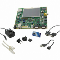
AT91SAM9M10-G45-EK
Description
KIT EVAL FOR AT91SAMG45/9M10
Manufacturer
Atmel
Series
AT91SAM Smart ARMr
Type
MCUr
Specifications of AT91SAM9M10-G45-EK
Contents
Board, Cables, Power Supply
Processor To Be Evaluated
AT91SAM9M10
Processor Series
AT91SAM9
Data Bus Width
32 bit
Interface Type
RS-232, Ethernet, USB, JTAG
Operating Supply Voltage
5 V
Silicon Manufacturer
Atmel
Core Architecture
AVR
Kit Contents
Board
Features
Two High Speed USB Hosts, LCD TFT Display
Svhc
No SVHC (15-Dec-2010)
Mcu Supported Families
AT91SAM9M10,
Rohs Compliant
Yes
For Use With/related Products
AT91SAM9M10
Lead Free Status / RoHS Status
Lead free / RoHS Compliant
Available stocks
Company
Part Number
Manufacturer
Quantity
Price
Company:

Part Number:
AT91SAM9M10-G45-EK
Manufacturer:
INFINEON
Quantity:
10 000
Company:
Part Number:
AT91SAM9M10-G45-EK
Manufacturer:
Atmel
Quantity:
135


6495B–ATARM–21-Apr-10
Board Description
Figure 4-17. SD/MMC0
Figure 4-18. SD/MMC1
4.2.13
4-20
TFT LCD with Touch Panel
PA[22..31]
The SAM9M10 features an LCD controller. A 4.3" 480x272 Portrait Mode LCD provides the SAM9M10-
G45-EK with a low power LCD display, back light unit and a touch panel, similar to that used on commer-
cial PDAs.
The TFT LCD component is a truly model number TFT1N4633.
Graphics and text can be displayed on the dot matrix panel with up to 16 million colors by supplying 24-
bit data signals (8bitxRGB by default) or 16-bit data signals (5+6+5bitxRGB in option). This allows the
user to develop graphical user interfaces for a wide variety of end applications.
Warning: never connect/disconnect the LCD display from the board while the power supply is on. Doing
so may damage both units and is not covered by warranty.
The back light voltage is generated from a CP2122ST boost converter. It is powered directly by the VIN
5 VCC power (the control for the back light voltages is separated from the main board voltages due to
the specific voltage requirements of the LCD panel).
PD29
PD11
PA[0..5]
PD10
PA24
PA23
PA31
PA22
PA26
PA25
PA27
PA28
PA29
PA30
PA3
PA2
PA0
PA1
PA5
PA4
(MCI1_W P)
(MCI1_CD)
(MCI1_DA1)
(MCI1_DA0)
(MCI1_CK)
(MCI1_CDA)
(MCI1_DA3)
(MCI1_DA2)
(MCI1_DA4)
(MCI1_DA5)
(MCI1_DA6)
(MCI1_DA7)
(MCI0_CD)
(MCI0_DA1)
(MCI0_DA0)
(MCI0_CK)
(MCI0_CDA)
(MCI0_DA3)
(MCI0_DA2)
R64
R64
10k
10k
1
2
3
4
1
2
3
4
1
2
3
4
RR40
RR40
RR39
RR39
RR42
RR42
1
2
3
4
1
2
3
4
RR41
RR41
RR38 27R
RR38 27R
8
7
6
5
8
7
6
5
8
7
6
5
27R
27R
8
7
6
5
8
7
6
5
27R
27R
27R
27R
27R
27R
R191
R191
68k
68k
R187
R187
68k
68k
R192
R192
68k
68k
R188
R188
68k
68k
R193
R193
68k
68k
R189
R189
68k
68k
R194
R194
68k
68k
R190
R190
68k
68k
SD/MMC CARD INTERFACE - MCI0
R195
R195
68k
68k
3V3
R196
R196
68k
68k
SD/MMCPlus CARD INTERFACE - MCI1
3V3
3V3
R65
R65
10k
10k
R197
R197
68k
68k
R198
R198
68k
68k
C122 100n
C122 100n
3V3
100n
100n
RR36
RR36
10k
10k
C123
C123
8
7
6
5
4
3
2
1
9
J6
J6
8
7
6
5
4
3
2
1
9
J5
J5
AT91SAM9M10-G45-EK User Guide
12
11
10
16
15
14
13
12
11
10
Related parts for AT91SAM9M10-G45-EK
Image
Part Number
Description
Manufacturer
Datasheet
Request
R

Part Number:
Description:
KIT EVAL FOR AT91SAM9M10
Manufacturer:
Atmel
Datasheet:

Part Number:
Description:
IC MCU 16/32BIT ARM9 324TFBGA
Manufacturer:
Atmel
Datasheet:

Part Number:
Description:
At91 Arm Thumb-based Microcontrollers
Manufacturer:
ATMEL Corporation
Datasheet:

Part Number:
Description:
MCU, MPU & DSP Development Tools KICKSTART KIT FOR AT91SAM9 PLUS
Manufacturer:
IAR Systems

Part Number:
Description:
DEV KIT FOR AVR/AVR32
Manufacturer:
Atmel
Datasheet:
Part Number:
Description:
INTERVAL AND WIPE/WASH WIPER CONTROL IC WITH DELAY
Manufacturer:
ATMEL Corporation
Datasheet:
Part Number:
Description:
Low-Voltage Voice-Switched IC for Hands-Free Operation
Manufacturer:
ATMEL Corporation
Datasheet:
Part Number:
Description:
MONOLITHIC INTEGRATED FEATUREPHONE CIRCUIT
Manufacturer:
ATMEL Corporation
Datasheet:
Part Number:
Description:
AM-FM Receiver IC U4255BM-M
Manufacturer:
ATMEL Corporation
Datasheet:
Part Number:
Description:
Monolithic Integrated Feature Phone Circuit
Manufacturer:
ATMEL Corporation
Datasheet:
Part Number:
Description:
Multistandard Video-IF and Quasi Parallel Sound Processing
Manufacturer:
ATMEL Corporation
Datasheet:
Part Number:
Description:
High-performance EE PLD
Manufacturer:
ATMEL Corporation
Datasheet: