AT91SAM9M10-G45-EK Atmel, AT91SAM9M10-G45-EK Datasheet - Page 35
AT91SAM9M10-G45-EK
Manufacturer Part Number
AT91SAM9M10-G45-EK
Description
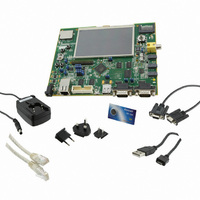
KIT EVAL FOR AT91SAMG45/9M10
Manufacturer
Atmel
Series
AT91SAM Smart ARMr
Type
MCUr
Specifications of AT91SAM9M10-G45-EK
Contents
Board, Cables, Power Supply
Processor To Be Evaluated
AT91SAM9M10
Processor Series
AT91SAM9
Data Bus Width
32 bit
Interface Type
RS-232, Ethernet, USB, JTAG
Operating Supply Voltage
5 V
Silicon Manufacturer
Atmel
Core Architecture
AVR
Kit Contents
Board
Features
Two High Speed USB Hosts, LCD TFT Display
Svhc
No SVHC (15-Dec-2010)
Mcu Supported Families
AT91SAM9M10,
Rohs Compliant
Yes
For Use With/related Products
AT91SAM9M10
Lead Free Status / RoHS Status
Lead free / RoHS Compliant
Available stocks
Company
Part Number
Manufacturer
Quantity
Price
Company:

Part Number:
AT91SAM9M10-G45-EK
Manufacturer:
INFINEON
Quantity:
10 000
Company:
Part Number:
AT91SAM9M10-G45-EK
Manufacturer:
Atmel
Quantity:
135


5.4
5.5
5.5.1
5.5.2
AT91SAM9M10-G45-EK User Guide
Miscellaneous Configuration Items
PIO Configuration
Peripheral Signals Multiplexing on I/O Lines
Multiplexing on PIO Controller A (PIOA)
N.P = not populated
P = populated
Table 5-3. Miscellaneous Configuration
The AT91SAM9M10 product features 5 PIO controllers, PIOA, PIOB, PIOC, PIOD and PIOE, which mul-
tiplex the I/O lines of the peripheral set. Each PIO Controller controls up to 32 lines. Each line can be
assigned to one of two peripheral functions, A or B. The multiplexing tables in the following paragraphs
define how the I/O lines of peripherals A and B are multiplexed on the PIO Controllers.
"R.Select" = connection selectable via an on-board resistor (default not populated)
Designation
R110, R112,
R114, C174,
R100, R103
Y6, R184,
C175, Y5
R91,R92
R93,R94
to R105,
R108 to
R186
R34
R35
R36
R38
R63
R68
R75
TP1
TP2
TP3
TP4
Default
Setting
N.P
N.P
N.P
N.P
N.P
P
P
P
JTAGSEL
Connect TSADVREF to VDDANA (may be used for specific filtering)
Connect GNDANA to GND (may be used for specific filtering)
Force TST pin to GND (chip is set in non-test mode = normal operation mode)
Write protect NAND Flash (mount a 0-ohm resistor to write-protect the NAND
Flash device)
Write protect serial DataFlash (mount a 0-ohm resistor to write-protect the serial
Flash device)
External clock Audio AC97 (mount a 0-ohm resistor to connect it)
ICE interface reset and clocking schemes (see
Configuration”
Ethernet interface, MII mode (see
External 13 MHz oscillator (option) for the on-board video composite encoder
GND Test point
GND Test point
GND Test point
GND Test point
)
Section 5.2 ”ETHERNET Configuration”
Feature
Section 5.1 ”JTAG/ICE
6495B–ATARM–21-Apr-10
Configuration
5-3
)
Related parts for AT91SAM9M10-G45-EK
Image
Part Number
Description
Manufacturer
Datasheet
Request
R

Part Number:
Description:
KIT EVAL FOR AT91SAM9M10
Manufacturer:
Atmel
Datasheet:

Part Number:
Description:
IC MCU 16/32BIT ARM9 324TFBGA
Manufacturer:
Atmel
Datasheet:

Part Number:
Description:
At91 Arm Thumb-based Microcontrollers
Manufacturer:
ATMEL Corporation
Datasheet:

Part Number:
Description:
MCU, MPU & DSP Development Tools KICKSTART KIT FOR AT91SAM9 PLUS
Manufacturer:
IAR Systems

Part Number:
Description:
DEV KIT FOR AVR/AVR32
Manufacturer:
Atmel
Datasheet:
Part Number:
Description:
INTERVAL AND WIPE/WASH WIPER CONTROL IC WITH DELAY
Manufacturer:
ATMEL Corporation
Datasheet:
Part Number:
Description:
Low-Voltage Voice-Switched IC for Hands-Free Operation
Manufacturer:
ATMEL Corporation
Datasheet:
Part Number:
Description:
MONOLITHIC INTEGRATED FEATUREPHONE CIRCUIT
Manufacturer:
ATMEL Corporation
Datasheet:
Part Number:
Description:
AM-FM Receiver IC U4255BM-M
Manufacturer:
ATMEL Corporation
Datasheet:
Part Number:
Description:
Monolithic Integrated Feature Phone Circuit
Manufacturer:
ATMEL Corporation
Datasheet:
Part Number:
Description:
Multistandard Video-IF and Quasi Parallel Sound Processing
Manufacturer:
ATMEL Corporation
Datasheet:
Part Number:
Description:
High-performance EE PLD
Manufacturer:
ATMEL Corporation
Datasheet: