AT91SAM9M10-G45-EK Atmel, AT91SAM9M10-G45-EK Datasheet - Page 34
AT91SAM9M10-G45-EK
Manufacturer Part Number
AT91SAM9M10-G45-EK
Description
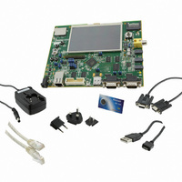
KIT EVAL FOR AT91SAMG45/9M10
Manufacturer
Atmel
Series
AT91SAM Smart ARMr
Type
MCUr
Specifications of AT91SAM9M10-G45-EK
Contents
Board, Cables, Power Supply
Processor To Be Evaluated
AT91SAM9M10
Processor Series
AT91SAM9
Data Bus Width
32 bit
Interface Type
RS-232, Ethernet, USB, JTAG
Operating Supply Voltage
5 V
Silicon Manufacturer
Atmel
Core Architecture
AVR
Kit Contents
Board
Features
Two High Speed USB Hosts, LCD TFT Display
Svhc
No SVHC (15-Dec-2010)
Mcu Supported Families
AT91SAM9M10,
Rohs Compliant
Yes
For Use With/related Products
AT91SAM9M10
Lead Free Status / RoHS Status
Lead free / RoHS Compliant
Available stocks
Company
Part Number
Manufacturer
Quantity
Price
Company:

Part Number:
AT91SAM9M10-G45-EK
Manufacturer:
INFINEON
Quantity:
10 000
Company:
Part Number:
AT91SAM9M10-G45-EK
Manufacturer:
Atmel
Quantity:
135


6495B–ATARM–21-Apr-10
Configuration
5.3
Table 5-2. Jumpers Configuration
5-2
jumper array)
Designation
JP17-JP18
(combined
JP10
JP11
JP12
JP13
JP14
JP15
JP16
JP1
JP2
JP3
JP4
JP5
JP6
JP7
JP8
JP9
J1
Jumpers Configuration
Test points
Test point
Two types of jumpers are used on the SAM9M10-G45-EK board:
Opened
Opened
Opened
Default
Setting
Closed
Closed
Closed
Closed
Closed
Closed
Closed
Closed
2-pin jumpers with two possible settings:
3-pin jumpers with two possible positions, for which settings are presented in the following tables.
1-2
1-2
1-2
1-2
1-2
1-2
– Fitted: the circuit is closed
– Not fitted: the circuit is open
Forces power on.
To use the software shutdown control, JP4 must be opened.
3V battery backup must be present and JP7 jumper set in position 1-2
BMS Enables Boot on the internal ROM; closed selects the boot from the external device connected
to NCS0
Enables chip select access, Boot on the NCS0 (MN10 Flash)
Enables chip select access, Boot on the NCS3 (MN11 NAND Flash)
Enables chip select access, Boot on the SPIO_NPCS0 (Serial DataFlash MN13)
Set address A0 low (MN12 Serial EEPROM), enable Boot access.
Used to connect a Loudspeaker
DISMDIX (MN18)
Give access to the four GPIOs of WM9711L
J1-1
J1-2
J1-3
J1-4
JP1
JP2
JP3
JP5
JP6
JP7
JP14.1 = Line_Out
JP11.1: SO
1-2
3-4
5-6
7-8
1-2
2-3
1-2
2-3
1-2
2-3
1-2
2-3
1-2
2-3
1-2
2-3
VDDUTMII
VDDUTIMC
VDDCORE
VDDPLLUTMI
VDDIOP0
External power to VDDIOP0
VDDIOP1
External power to VDDIOP1
VDDIOP2
External power to VDDIOP2
VDDIOM0
External power to VDDIOM0
VDDIOM1
External power to VDDIOM1
VDDBU
VDDBU
Feature
JP11.2: SI
JP14.3 = AGND
AT91SAM9M10-G45-EK User Guide
3.3V from regulator
Lithium 3V Battery
JP11.3: SCK
3V3 nominal
3V3 nominal
3V3 nominal
1V8 nominal
1V8 nominal
3V3
3V3
3V3
3V3
1V8
1V8
1V
1V
1V
Related parts for AT91SAM9M10-G45-EK
Image
Part Number
Description
Manufacturer
Datasheet
Request
R

Part Number:
Description:
KIT EVAL FOR AT91SAM9M10
Manufacturer:
Atmel
Datasheet:

Part Number:
Description:
IC MCU 16/32BIT ARM9 324TFBGA
Manufacturer:
Atmel
Datasheet:

Part Number:
Description:
At91 Arm Thumb-based Microcontrollers
Manufacturer:
ATMEL Corporation
Datasheet:

Part Number:
Description:
MCU, MPU & DSP Development Tools KICKSTART KIT FOR AT91SAM9 PLUS
Manufacturer:
IAR Systems

Part Number:
Description:
DEV KIT FOR AVR/AVR32
Manufacturer:
Atmel
Datasheet:
Part Number:
Description:
INTERVAL AND WIPE/WASH WIPER CONTROL IC WITH DELAY
Manufacturer:
ATMEL Corporation
Datasheet:
Part Number:
Description:
Low-Voltage Voice-Switched IC for Hands-Free Operation
Manufacturer:
ATMEL Corporation
Datasheet:
Part Number:
Description:
MONOLITHIC INTEGRATED FEATUREPHONE CIRCUIT
Manufacturer:
ATMEL Corporation
Datasheet:
Part Number:
Description:
AM-FM Receiver IC U4255BM-M
Manufacturer:
ATMEL Corporation
Datasheet:
Part Number:
Description:
Monolithic Integrated Feature Phone Circuit
Manufacturer:
ATMEL Corporation
Datasheet:
Part Number:
Description:
Multistandard Video-IF and Quasi Parallel Sound Processing
Manufacturer:
ATMEL Corporation
Datasheet:
Part Number:
Description:
High-performance EE PLD
Manufacturer:
ATMEL Corporation
Datasheet: