CAN-100 Fujitsu Semiconductor America Inc, CAN-100 Datasheet - Page 83
CAN-100
Manufacturer Part Number
CAN-100
Description
BOARD EVAL RS232 100QFP
Manufacturer
Fujitsu Semiconductor America Inc
Series
FRr
Type
MCUr
Specifications of CAN-100
Contents
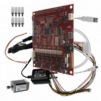
Board, BLDC Motor, Cables, Power Supply
For Use With/related Products
MB91F267N
Lead Free Status / RoHS Status
Lead free / RoHS Compliant
Other names
865-1102
Available stocks
Company
Part Number
Manufacturer
Quantity
Price
Company:

Part Number:
CAN-100
Manufacturer:
Fujitsu Semiconductor America
Quantity:
135


The features of CAN can be classified into the following five points.
1. Multi-master communication
2. Bus-type topology
3. Differential transmission system
CAN employs the multi-master system in which each node is allowed to start communication as
desired. The timing of a start of communication is occurrence of an event. The word “event”
mentioned here indicates an occasion at which a node needs to start communication.
CAN avoid conflicts in communication through mediation with node signals if more than one
event occurs on nodes simultaneously. This mediation is called arbitration.
The CAN topology is the bus type. The maximum number of nodes depends on the
communication speed; in the case of 1M bits/sec, up to 30 nodes are allowed. This is specified as
a regulation.
Taking account of influence from noise on the transmission paths, CAN employs the differential
transmission system in which the voltage difference between two signal lines is used to
determine “0”/”1”. The signal lines are respectively called CANH and CANL and the voltage
difference between them is used to determine the bus level. The differential is used to determine
logical “0”/”1”. As shown in “Figure 5-2 CAN bus signal levels”, the bus status of logical “0” is
called dominant and the bus status of logical “1” is called recessive. The communicable distance
depends on the communication speed; in the case of 1M bits/sec, up to 40 m is allowed. This is
also specified by a regulation.
Voltage
Logical “1”
Recessive
Figure 5-2 CAN bus signal levels
Logical “0”
Dominant
- 83 -
Logical “1”
Recessive
AN07-00180-3E
Related parts for CAN-100
Image
Part Number
Description
Manufacturer
Datasheet
Request
R

Part Number:
Description:
IC POWER SUPPLY MONITOR 8SOP
Manufacturer:
Fujitsu Semiconductor America Inc
Datasheet:
Part Number:
Description:
IC POWER SUPPLY MONITOR 8SOP
Manufacturer:
Fujitsu Semiconductor America Inc
Datasheet:

Part Number:
Description:
IC MCU 60K FLASH 2KB RAM 52LQFP
Manufacturer:
Fujitsu Semiconductor America Inc
Datasheet:

Part Number:
Description:
IC MCU 32BIT 256KB FLASH 120LQFP
Manufacturer:
Fujitsu Semiconductor America Inc
Datasheet:
Part Number:
Description:
IC CTLR TOUCH SENSOR 12CH 30SSOP
Manufacturer:
Fujitsu Semiconductor America Inc
Datasheet:

Part Number:
Description:
IC CTLR TOUCH SENSOR 12CH 40QFN
Manufacturer:
Fujitsu Semiconductor America Inc
Datasheet:
Part Number:
Description:
SYNTHESIZER PLL DUAL INP 20SSOP
Manufacturer:
Fujitsu Semiconductor America Inc
Datasheet:

Part Number:
Description:
SYNTHESZR PLL 1.1GHZ DUAL 16SSOP
Manufacturer:
Fujitsu Semiconductor America Inc
Datasheet:

Part Number:
Description:
IC SSCG EMI RED 8-SOIC
Manufacturer:
Fujitsu Semiconductor America Inc
Datasheet:

Part Number:
Description:
IC SSCG EMI RED 8-TSSOP
Manufacturer:
Fujitsu Semiconductor America Inc
Datasheet:

Part Number:
Description:
IC SSCG EMI RED 8-SOP
Manufacturer:
Fujitsu Semiconductor America Inc
Datasheet:

Part Number:
Description:
SYNTHESIZER PLL 2.5GHZ 16SSOP
Manufacturer:
Fujitsu Semiconductor America Inc
Datasheet:
Part Number:
Description:
SYNTHESIZER PLL 1.2GHZ 16SSOP
Manufacturer:
Fujitsu Semiconductor America Inc
Datasheet:

Part Number:
Description:
SYNTHESIZER PLL 2.5GHZ 16BCC
Manufacturer:
Fujitsu Semiconductor America Inc
Datasheet:

Part Number:
Description:
IC SSCG EMI RED 8-SOP
Manufacturer:
Fujitsu Semiconductor America Inc
Datasheet: