101-1226 Rabbit Semiconductor, 101-1226 Datasheet - Page 27
101-1226
Manufacturer Part Number
101-1226
Description
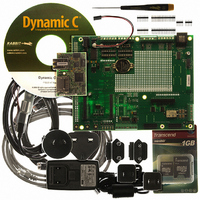
RCM3900 DEV KIT UNIVERSAL
Manufacturer
Rabbit Semiconductor
Series
RabbitCore 3900r
Type
MPU Moduler
Datasheet
1.20-101-1196.pdf
(168 pages)
Specifications of 101-1226
Contents
RabbitCore Module, Dev. Board, AC Adapter, Cable and Dynamic C® CD-Rom
For Use With/related Products
RCM3900
Lead Free Status / RoHS Status
Lead free / RoHS Compliant
Other names
316-1137


4.1 RCM3900 Inputs and Outputs
Figure 5 shows the RCM3900 pinouts for headers J61 and J62.
Figure 5. RCM3900 Pinouts
The
RCM3300/RCM3305/
pinouts for the RCM3000, RCM3100, RCM3200,
RCM3309/
RCM3365/RCM3375, and RCM3900
RCM3319, RCM3360/RCM3370,
are almost compati-
ble, except signals PB0, PC4, and PC5. are used for the SPI interface to the serial flash on the
RCM3305/
RCM3309/RCM3315/RCM3319 and for the microSD™ Card on the RCM3900/
, but are available on the other modules.
RCM3910
Headers J61 and J62 are standard 2 × 17 headers with a nominal 2 mm pitch. An RJ-45
Ethernet port is also included with the RCM3900.
Pins 29–32 on header J61 are configured using 0 resistors at locations JP9, JP10, JP7,
and JP8 to enable connections to PD2, PD3, PD6, and PD7 respectively. Note that there is
no 0 resistor at location JP9 since PD2/TPO– is not available on header J61. They may
also be reconfigured to carry the Ethernet signals TPO–, TPO+, TPI–, and TPI+, but this
capability is reserved for future use.
Pins 33 and 34 on header J61 are wired via 0 surface-mount resistors at JP2 and JP3 to
carry the
ACT
and
LINK
signals that illuminate the corresponding LEDs on the RCM3900
module. These pins may be “configured” to carry PD0 and PD1, an option that is reserved
for future use.
See Appendix A.6 for more information about the locations of these headers.
RabbitCore RCM3900 User’s Manual
27
Related parts for 101-1226
Image
Part Number
Description
Manufacturer
Datasheet
Request
R

Part Number:
Description:
COMPUTER SNGLBD BL2120 FRCTNLOCK
Manufacturer:
Rabbit Semiconductor
Datasheet:

Part Number:
Description:
KIT APPLCTN RABBITCORE RCM4010
Manufacturer:
Rabbit Semiconductor
Datasheet:

Part Number:
Description:
KIT MESH NETWORK ADD-ON RCM4510W
Manufacturer:
Rabbit Semiconductor
Datasheet:

Part Number:
Description:
KIT DEV FOR BL2500 COYOTE
Manufacturer:
Rabbit Semiconductor
Datasheet:

Part Number:
Description:
KIT APPLICATION SIMPLE SENSOR
Manufacturer:
Rabbit Semiconductor
Datasheet:

Part Number:
Description:
KIT DEV RABBITCORE RCM3750
Manufacturer:
Rabbit Semiconductor
Datasheet:

Part Number:
Description:
KIT DEV RABBIT 2000 INT'L
Manufacturer:
Rabbit Semiconductor
Datasheet:
Part Number:
Description:
KIT DEV RABBIT RCM2000 INT'L
Manufacturer:
Rabbit Semiconductor
Datasheet:

Part Number:
Description:
KIT DEVELOPMENT RCM3700 INT'L
Manufacturer:
Rabbit Semiconductor
Datasheet:
Part Number:
Description:
MODULE RABBITCORE RCM3720
Manufacturer:
Rabbit Semiconductor
Datasheet:
Part Number:
Description:
MODULE RABBITCORE RCM3220
Manufacturer:
Rabbit Semiconductor
Datasheet:
Part Number:
Description:
MODULE RABBITCORE RCM3210
Manufacturer:
Rabbit Semiconductor
Datasheet:
Part Number:
Description:
COMPUTER SGL-BOARD OP6600 W/SRAM
Manufacturer:
Rabbit Semiconductor
Datasheet:
Part Number:
Description:
COMPUTER SGL-BD BL2000 SRAM/FLSH
Manufacturer:
Rabbit Semiconductor