101-1226 Rabbit Semiconductor, 101-1226 Datasheet - Page 87
101-1226
Manufacturer Part Number
101-1226
Description
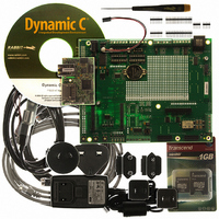
RCM3900 DEV KIT UNIVERSAL
Manufacturer
Rabbit Semiconductor
Series
RabbitCore 3900r
Type
MPU Moduler
Datasheet
1.20-101-1196.pdf
(168 pages)
Specifications of 101-1226
Contents
RabbitCore Module, Dev. Board, AC Adapter, Cable and Dynamic C® CD-Rom
For Use With/related Products
RCM3900
Lead Free Status / RoHS Status
Lead free / RoHS Compliant
Other names
316-1137


B.1.1 Prototyping Board Features
•
•
•
•
•
•
•
•
•
RabbitCore RCM3900 User’s Manual
Power Connection
nection to the power supply. Note that the 3-pin header is symmetrical, with both outer
pins connected to ground and the center pin connected to the raw V+ input. The cable
of the AC adapter provided with Development Kit ends in a 3-pin plug that connects to
the 3-pin header (J2)—the center pin of J2 is always connected to the positive terminal,
and either edge pin is negative.
Users providing their own power supply should ensure that it delivers 8–30 V DC at 1 A.
Regulated Power Supply
routed to a 5 V switching voltage regulator, then to a separate 3.3 V linear regulator.
The regulators provide stable power to the RCM3900 module and the Prototyping
Board. The voltage regulators will get warm while in use.
Power LED
Board.
Core LED
rectly on the Prototyping Board and the RCM3900 module is not being reset.
Relay LED
Reset Switch
RCM3900’s
I/O Switches and LEDs
nected to the PG0 and PG1 pins of the RCM3900 module and may be read as inputs by
sample applications.
Four user LEDs (DS3–DS6) are connected to alternate I/O bus pins PA0–PA3 pins of
the RCM3900 module via U8, and may be driven as output indicators. PE7 and PG5
control the registers in U8 as shown in the sample applications.
Prototyping Area
of through-hole components. +3.3 V, +5 V, and Ground buses run along one edge of
this area. Several areas for surface-mount devices are also available. Each SMT pad is
connected to a hole designed to accept a 30 AWG solid wire.
LCD/Keypad Module
headers LCD1JA, LCD1JB, and LCD1JC. The signals on headers LCD1JB and
LCD1JC will be available only if the LCD/keypad module is plugged in to header
LCD1JA. Appendix C provides complete information for mounting and using the
LCD/keypad module.
—The core LED lights whenever an RCM3900 module is plugged in cor-
—The relay LED lights whenever the Prototyping Board relay is energized.
—The power LED lights whenever power is connected to the Prototyping
/RESET_IN
—A momentary-contact, normally open switch is connected directly to the
—A generous prototyping area has been provided for the installation
—A power-supply jack and a 3-pin header are provided for con-
—Rabbit’s LCD/keypad module may be plugged in directly to
pin. Pressing the switch forces a hardware reset of the system.
—Two momentary-contact, normally open switches are con-
—The raw DC voltage provided at the POWER IN jack is
87
Related parts for 101-1226
Image
Part Number
Description
Manufacturer
Datasheet
Request
R

Part Number:
Description:
COMPUTER SNGLBD BL2120 FRCTNLOCK
Manufacturer:
Rabbit Semiconductor
Datasheet:

Part Number:
Description:
KIT APPLCTN RABBITCORE RCM4010
Manufacturer:
Rabbit Semiconductor
Datasheet:

Part Number:
Description:
KIT MESH NETWORK ADD-ON RCM4510W
Manufacturer:
Rabbit Semiconductor
Datasheet:

Part Number:
Description:
KIT DEV FOR BL2500 COYOTE
Manufacturer:
Rabbit Semiconductor
Datasheet:

Part Number:
Description:
KIT APPLICATION SIMPLE SENSOR
Manufacturer:
Rabbit Semiconductor
Datasheet:

Part Number:
Description:
KIT DEV RABBITCORE RCM3750
Manufacturer:
Rabbit Semiconductor
Datasheet:

Part Number:
Description:
KIT DEV RABBIT 2000 INT'L
Manufacturer:
Rabbit Semiconductor
Datasheet:
Part Number:
Description:
KIT DEV RABBIT RCM2000 INT'L
Manufacturer:
Rabbit Semiconductor
Datasheet:

Part Number:
Description:
KIT DEVELOPMENT RCM3700 INT'L
Manufacturer:
Rabbit Semiconductor
Datasheet:
Part Number:
Description:
MODULE RABBITCORE RCM3720
Manufacturer:
Rabbit Semiconductor
Datasheet:
Part Number:
Description:
MODULE RABBITCORE RCM3220
Manufacturer:
Rabbit Semiconductor
Datasheet:
Part Number:
Description:
MODULE RABBITCORE RCM3210
Manufacturer:
Rabbit Semiconductor
Datasheet:
Part Number:
Description:
COMPUTER SGL-BOARD OP6600 W/SRAM
Manufacturer:
Rabbit Semiconductor
Datasheet:
Part Number:
Description:
COMPUTER SGL-BD BL2000 SRAM/FLSH
Manufacturer:
Rabbit Semiconductor