101-1226 Rabbit Semiconductor, 101-1226 Datasheet - Page 5
101-1226
Manufacturer Part Number
101-1226
Description
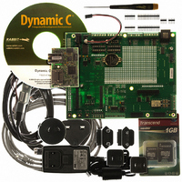
RCM3900 DEV KIT UNIVERSAL
Manufacturer
Rabbit Semiconductor
Series
RabbitCore 3900r
Type
MPU Moduler
Datasheet
1.20-101-1196.pdf
(168 pages)
Specifications of 101-1226
Contents
RabbitCore Module, Dev. Board, AC Adapter, Cable and Dynamic C® CD-Rom
For Use With/related Products
RCM3900
Lead Free Status / RoHS Status
Lead free / RoHS Compliant
Other names
316-1137


Appendix C. LCD/Keypad Module
Appendix D. Power Supply
Index
Schematics
RabbitCore RCM3900 User’s Manual
B.5 Prototyping Board Jumper Configurations ......................................................................................102
B.6 Use of Rabbit 3000 Parallel Ports ....................................................................................................104
C.1 Specifications ...................................................................................................................................106
C.2 Contrast Adjustments for All Boards ...............................................................................................108
C.3 Keypad Labeling ..............................................................................................................................109
C.4 Header Pinouts .................................................................................................................................110
C.5 Mounting LCD/Keypad Module on the Prototyping Board ............................................................111
C.6 Bezel-Mount Installation..................................................................................................................112
C.7 Sample Programs .............................................................................................................................115
C.8 LCD/Keypad Module Function Calls ..............................................................................................116
D.1 Power Supplies.................................................................................................................................161
B.4.1 Adding Other Components.........................................................................................................93
B.4.2 Digital I/O...................................................................................................................................94
B.4.3 CMOS Digital Outputs...............................................................................................................95
B.4.4 Sinking Digital Outputs..............................................................................................................95
B.4.5 Relay Outputs .............................................................................................................................95
B.4.6 Serial Communication................................................................................................................96
B.4.7 RabbitNet Port ............................................................................................................................99
B.4.8 Other Prototyping Board Modules ...........................................................................................100
B.4.9 Quadrature Decoder .................................................................................................................100
B.4.10 Stepper-Motor Control ...........................................................................................................100
C.4.1 I/O Address Assignments .........................................................................................................110
C.6.1 Connect the LCD/Keypad Module to Your Prototyping Board...............................................114
C.8.1 LCD/Keypad Module Initialization..........................................................................................116
C.8.2 LEDs.........................................................................................................................................117
C.8.3 LCD Display.............................................................................................................................118
C.8.4 Keypad......................................................................................................................................154
D.1.1 Battery Backup.........................................................................................................................161
D.1.2 Battery-Backup Circuit ............................................................................................................162
D.1.3 Reset Generator ........................................................................................................................163
B.4.2.1 Digital Inputs ..................................................................................................................... 94
B.4.6.1 RS-232 ............................................................................................................................... 97
B.4.6.2 RS-485 ............................................................................................................................... 98
106
161
164
168
5
Related parts for 101-1226
Image
Part Number
Description
Manufacturer
Datasheet
Request
R

Part Number:
Description:
COMPUTER SNGLBD BL2120 FRCTNLOCK
Manufacturer:
Rabbit Semiconductor
Datasheet:

Part Number:
Description:
KIT APPLCTN RABBITCORE RCM4010
Manufacturer:
Rabbit Semiconductor
Datasheet:

Part Number:
Description:
KIT MESH NETWORK ADD-ON RCM4510W
Manufacturer:
Rabbit Semiconductor
Datasheet:

Part Number:
Description:
KIT DEV FOR BL2500 COYOTE
Manufacturer:
Rabbit Semiconductor
Datasheet:

Part Number:
Description:
KIT APPLICATION SIMPLE SENSOR
Manufacturer:
Rabbit Semiconductor
Datasheet:

Part Number:
Description:
KIT DEV RABBITCORE RCM3750
Manufacturer:
Rabbit Semiconductor
Datasheet:

Part Number:
Description:
KIT DEV RABBIT 2000 INT'L
Manufacturer:
Rabbit Semiconductor
Datasheet:
Part Number:
Description:
KIT DEV RABBIT RCM2000 INT'L
Manufacturer:
Rabbit Semiconductor
Datasheet:

Part Number:
Description:
KIT DEVELOPMENT RCM3700 INT'L
Manufacturer:
Rabbit Semiconductor
Datasheet:
Part Number:
Description:
MODULE RABBITCORE RCM3720
Manufacturer:
Rabbit Semiconductor
Datasheet:
Part Number:
Description:
MODULE RABBITCORE RCM3220
Manufacturer:
Rabbit Semiconductor
Datasheet:
Part Number:
Description:
MODULE RABBITCORE RCM3210
Manufacturer:
Rabbit Semiconductor
Datasheet:
Part Number:
Description:
COMPUTER SGL-BOARD OP6600 W/SRAM
Manufacturer:
Rabbit Semiconductor
Datasheet:
Part Number:
Description:
COMPUTER SGL-BD BL2000 SRAM/FLSH
Manufacturer:
Rabbit Semiconductor