ADZS-BF518F-EZLITE Analog Devices Inc, ADZS-BF518F-EZLITE Datasheet - Page 14
ADZS-BF518F-EZLITE
Manufacturer Part Number
ADZS-BF518F-EZLITE
Description
KIT EZ LITE BF512F/14F/16F/18F
Manufacturer
Analog Devices Inc
Type
DSPr
Datasheet
1.ADZS-BF518F-EZBRD.pdf
(62 pages)
Specifications of ADZS-BF518F-EZLITE
Featured Product
Blackfin® BF50x Series Processors
Contents
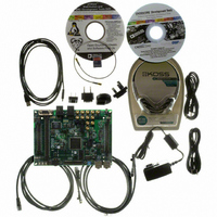
Board, Cables, CD, Head Phones, Power Supply
Silicon Manufacturer
Analog Devices
Core Architecture
Blackfin
Features
USB-based, PC-hosted Tool Set
Kit Contents
Brd, PSU, CD, Docs, SD Card, Cables
Silicon Family Name
Blackfin
Silicon Core Number
ADSP-BF518F
Rohs Compliant
Yes
Lead Free Status / RoHS Status
Lead free / RoHS Compliant
For Use With/related Products
BF512F/14F/16F/18F
For Use With
ADZS-BFBLUET-EZEXT - EZ-EXTENDER DAUGHTERBOARD
Lead Free Status / RoHS Status
Lead free / RoHS Compliant, Lead free / RoHS Compliant


ADSP-BF512/BF514/BF516/BF518(F)
PARALLEL PERIPHERAL INTERFACE (PPI)
The ADSP-BF512/BF514/BF516/BF518(F) processors provide a
parallel peripheral interface (PPI) that can connect directly to
parallel A/D and D/A converters, ITU-R-601/656 video encod-
ers and decoders, and other general-purpose peripherals. The
PPI consists of a dedicated input clock signal, up to three frame
synchronization signals, and up to 16 data signals.
In ITU-R-656 modes, the PPI receives and parses a data stream
of 8-bit or 10-bit data elements. On-chip decode of embedded
preamble control and synchronization information
is supported.
Three distinct ITU-R-656 modes are supported:
Though not explicitly supported, ITU-R-656 output functional-
ity can be achieved by setting up the entire frame structure
(including active video, blanking, and control information) in
memory and streaming the data out the PPI in a frame sync-less
mode. The processor’s 2-D DMA features facilitate this transfer
by allowing the static frame buffer (blanking and control codes)
to be placed in memory once, and simply updating the active
video information on a per-frame basis.
The general-purpose modes of the PPI are intended to suit a
wide variety of data capture and transmission applications. The
modes are divided into four main categories, each allowing up
to 16 bits of data transfer per PPI_CLK cycle:
These modes support ADC/DAC connections, as well as video
communication with hardware signalling. Many of the modes
support more than one level of frame synchronization. If
desired, a programmable delay can be inserted between asser-
tion of a frame sync and reception/transmission of data.
• Active video only mode – The PPI does not read in any
• Vertical blanking only mode – The PPI only transfers verti-
• Entire field mode – The entire incoming bitstream is read
• Data receive with internally generated frame syncs
• Data receive with externally generated frame syncs
• Data transmit with internally generated frame syncs
• Data transmit with externally generated frame syncs
data between the End of Active Video (EAV) and Start of
Active Video (SAV) preamble symbols, or any data present
during the vertical blanking intervals. In this mode, the
control byte sequences are not stored to memory; they are
filtered by the PPI.
cal blanking interval (VBI) data, as well as horizontal
blanking information and control byte sequences on
VBI lines.
in through the PPI. This includes active video, control pre-
amble sequences, and ancillary data that may be embedded
in horizontal and vertical blanking intervals.
Rev. PrE | Page 14 of 62 | March 2009
CODE SECURITY WITH LOCKBOX SECURE
TECHNOLOGY
A security system consisting of a blend of hardware and soft-
ware provides customers with a flexible and rich set of code
security features with Lockbox secure technology. Key features
include:
The security scheme is based upon the concept of authentica-
tion of digital signatures using standards-based algorithms and
provides a secure processing environment in which to execute
code and protect assets.
DYNAMIC POWER MANAGEMENT
The ADSP-BF512/BF514/BF516/BF518(F) processors provide
four operating modes, each with a different performance/power
profile. In addition, dynamic power management provides the
control functions to dynamically alter the processor core supply
voltage, further reducing power dissipation. When configured
for a 0 volt core supply voltage, the processor enters the hiber-
nate state. Control of clocking to each of the processor
peripherals also reduces power consumption. See
summary of the power settings for each mode.
Table 4. Power Settings
Full-On Operating Mode—Maximum Performance
In the full-on mode, the PLL is enabled and is not bypassed,
providing capability for maximum operational frequency. This
is the power-up default execution state in which maximum per-
formance can be achieved. The processor core and all enabled
peripherals run at full speed.
Active Operating Mode—Moderate Power Savings
In the active mode, the PLL is enabled but bypassed. Because the
PLL is bypassed, the processor’s core clock (CCLK) and system
clock (SCLK) run at the input clock (CLKIN) frequency. In this
mode, the CLKIN to CCLK multiplier ratio can be changed,
although the changes are not realized until the full-on mode is
entered. DMA access is available to appropriately configured
L1 memories.
Mode/State PLL
Full On
Active
Sleep
Deep Sleep
Hibernate
• OTP memory
• Unique chip ID
• Code authentication
• Secure mode of operation
Enabled No
Enabled/
Disabled
Enabled —
Disabled —
Disabled —
Preliminary Technical Data
PLL
Bypassed
Yes
Core
Clock
(CCLK)
Enabled Enabled On
Enabled Enabled On
Disabled Enabled On
Disabled Disabled On
Disabled Disabled Off
System
Clock
(SCLK)
Table 4
Core
Power
for a
Related parts for ADZS-BF518F-EZLITE
Image
Part Number
Description
Manufacturer
Datasheet
Request
R

Part Number:
Description:
BOARD EVAL BF512F/14F/16F/18F
Manufacturer:
Analog Devices Inc
Datasheet:

Part Number:
Description:
USB EZ-Extender For Blackfin And SHARC EZ-Boards/EZ-KIT Lites
Manufacturer:
Analog Devices Inc

Part Number:
Description:
±1.7g Dual-Axis IMEMS Accelerometer Evaluation Board
Manufacturer:
Analog Devices Inc
Datasheet:
Part Number:
Description:
Inertial Sensor Evaluation System
Manufacturer:
Analog Devices Inc
Datasheet:
Part Number:
Description:
Manufacturer:
Analog Devices Inc
Datasheet:
Part Number:
Description:
Manufacturer:
Analog Devices Inc
Datasheet:
Part Number:
Description:
Manufacturer:
Analog Devices Inc
Datasheet:
Part Number:
Description:
Manufacturer:
Analog Devices Inc
Datasheet:
Part Number:
Description:
Manufacturer:
Analog Devices Inc
Datasheet:
Part Number:
Description:
Manufacturer:
Analog Devices Inc
Datasheet:
Part Number:
Description:
Manufacturer:
Analog Devices Inc
Datasheet:
Part Number:
Description:
Manufacturer:
Analog Devices Inc
Datasheet:
Part Number:
Description:
Manufacturer:
Analog Devices Inc
Datasheet: