ADZS-BF518F-EZLITE Analog Devices Inc, ADZS-BF518F-EZLITE Datasheet - Page 6
ADZS-BF518F-EZLITE
Manufacturer Part Number
ADZS-BF518F-EZLITE
Description
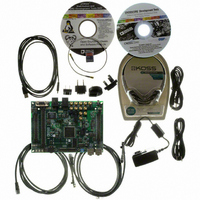
KIT EZ LITE BF512F/14F/16F/18F
Manufacturer
Analog Devices Inc
Type
DSPr
Datasheet
1.ADZS-BF518F-EZBRD.pdf
(62 pages)
Specifications of ADZS-BF518F-EZLITE
Featured Product
Blackfin® BF50x Series Processors
Contents
Board, Cables, CD, Head Phones, Power Supply
Silicon Manufacturer
Analog Devices
Core Architecture
Blackfin
Features
USB-based, PC-hosted Tool Set
Kit Contents
Brd, PSU, CD, Docs, SD Card, Cables
Silicon Family Name
Blackfin
Silicon Core Number
ADSP-BF518F
Rohs Compliant
Yes
Lead Free Status / RoHS Status
Lead free / RoHS Compliant
For Use With/related Products
BF512F/14F/16F/18F
For Use With
ADZS-BFBLUET-EZEXT - EZ-EXTENDER DAUGHTERBOARD
Lead Free Status / RoHS Status
Lead free / RoHS Compliant, Lead free / RoHS Compliant


ADSP-BF512/BF514/BF516/BF518(F)
The asynchronous memory controller can be programmed to
control up to four banks of devices with very flexible timing
parameters for a wide variety of devices. Each bank occupies a
1M byte segment regardless of the size of the devices used, so
that these banks are only contiguous if each is fully populated
with 1M byte of memory.
Flash Memory
The ADSP-BF512F/ADSP-BF514F/ADSP-BF516F/
ADSP-BF518F processors contain a SPI flash memory within
the package of the processor and connected to SPI0.
The SPI flash memory has a 4M bit capacity and 1.8V (nominal)
operating voltage. The program/erase endurance is 100,000
cycles per block, and this memory has greater than 100 years
data retention capability. Also included are support for software
write protection and support for fast erase and byte-program.
The processors internally connect to the flash memory die with
the MOSI, MISO, SPISSEL, and SPI_CLK signals similar to an
external SPI flash. To further provide a secure processing envi-
ronment, these internally connected signals are not exposed
outside of the package. For this reason, programming the
ADSP-BF51xF flash memory is performed by running code on
the processor. It cannot be programmed from external signals
and data transfers between the SPI flash and the processor can-
not be probed externally.
One-Time Programmable Memory
The processors have 64K bits of one-time programmable non-
volatile memory that can be programmed by the developer only
one time. It includes the array and logic to support read access
and programming. Additionally, its pages can be write
protected.
OTP enables developers to store both public and private data
on-chip. In addition to storing public and private key data for
applications requiring security, it also allows developers to store
completely user-definable data such as customer ID, product
ID, and MAC address. Hence generic parts can be shipped
which are then programmed and protected by the developer
within this non-volatile memory.
I/O Memory Space
The processors do not define a separate I/O space. All resources
are mapped through the flat 32-bit address space. On-chip I/O
devices have their control registers mapped into memory-
mapped registers (MMRs) at addresses near the top of the
4G byte address space. These are separated into two smaller
blocks, one which contains the control MMRs for all core func-
tions, and the other which contains the registers needed for
setup and control of the on-chip peripherals outside of the core.
The MMRs are accessible only in supervisor mode and appear
as reserved space to on-chip peripherals.
Rev. PrE | Page 6 of 62 | March 2009
Booting
The processors contain a small on-chip boot kernel, which con-
figures the appropriate peripheral for booting. If the processors
are configured to boot from boot ROM memory space, the pro-
cessor starts executing from the on-chip boot ROM. For more
information, see
Event Handling
The event controller handles all asynchronous and synchronous
events to the processor. The processors provide event handling
that supports both nesting and prioritization. Nesting allows
multiple event service routines to be active simultaneously. Pri-
oritization ensures that servicing of a higher-priority event takes
precedence over servicing of a lower-priority event. The con-
troller provides support for five different types of events:
Each event type has an associated register to hold the return
address and an associated return-from-event instruction. When
an event is triggered, the state of the processor is saved on the
supervisor stack.
The event controller consists of two stages, the core event con-
troller (CEC) and the system interrupt controller (SIC). The
core event controller works with the system interrupt controller
to prioritize and control all system events. Conceptually, inter-
rupts from the peripherals enter into the SIC, and are then
routed directly into the general-purpose interrupts of the CEC.
Core Event Controller (CEC)
The CEC supports nine general-purpose interrupts (IVG15–7),
in addition to the dedicated interrupt and exception events. Of
these general-purpose interrupts, the two lowest-priority
interrupts (IVG15–14) are recommended to be reserved for
software interrupt handlers, leaving seven prioritized interrupt
inputs to support the peripherals of the processors.
describes the inputs to the CEC, identifies their names in the
event vector table (EVT), and lists their priorities.
• Emulation – An emulation event causes the processor to
• Reset – This event resets the processor.
• Nonmaskable Interrupt (NMI) – The NMI event can be
• Exceptions – Events that occur synchronously to program
• Interrupts – Events that occur asynchronously to program
enter emulation mode, allowing command and control of
the processor through the JTAG interface.
generated by the software watchdog timer or by the NMI
input signal to the processor. The NMI event is frequently
used as a power-down indicator to initiate an orderly shut-
down of the system.
flow; that is, the exception is taken before the instruction is
allowed to complete. Conditions such as data alignment
violations and undefined instructions cause exceptions.
flow. They are caused by input signals, timers, and other
peripherals, as well as by an explicit software instruction.
Booting Modes on Page
Preliminary Technical Data
17.
Table 2
Related parts for ADZS-BF518F-EZLITE
Image
Part Number
Description
Manufacturer
Datasheet
Request
R

Part Number:
Description:
BOARD EVAL BF512F/14F/16F/18F
Manufacturer:
Analog Devices Inc
Datasheet:

Part Number:
Description:
USB EZ-Extender For Blackfin And SHARC EZ-Boards/EZ-KIT Lites
Manufacturer:
Analog Devices Inc

Part Number:
Description:
±1.7g Dual-Axis IMEMS Accelerometer Evaluation Board
Manufacturer:
Analog Devices Inc
Datasheet:
Part Number:
Description:
Inertial Sensor Evaluation System
Manufacturer:
Analog Devices Inc
Datasheet:
Part Number:
Description:
Manufacturer:
Analog Devices Inc
Datasheet:
Part Number:
Description:
Manufacturer:
Analog Devices Inc
Datasheet:
Part Number:
Description:
Manufacturer:
Analog Devices Inc
Datasheet:
Part Number:
Description:
Manufacturer:
Analog Devices Inc
Datasheet:
Part Number:
Description:
Manufacturer:
Analog Devices Inc
Datasheet:
Part Number:
Description:
Manufacturer:
Analog Devices Inc
Datasheet:
Part Number:
Description:
Manufacturer:
Analog Devices Inc
Datasheet:
Part Number:
Description:
Manufacturer:
Analog Devices Inc
Datasheet:
Part Number:
Description:
Manufacturer:
Analog Devices Inc
Datasheet: