ADZS-BF518F-EZLITE Analog Devices Inc, ADZS-BF518F-EZLITE Datasheet - Page 9
ADZS-BF518F-EZLITE
Manufacturer Part Number
ADZS-BF518F-EZLITE
Description
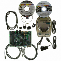
KIT EZ LITE BF512F/14F/16F/18F
Manufacturer
Analog Devices Inc
Type
DSPr
Datasheet
1.ADZS-BF518F-EZBRD.pdf
(62 pages)
Specifications of ADZS-BF518F-EZLITE
Featured Product
Blackfin® BF50x Series Processors
Contents
Board, Cables, CD, Head Phones, Power Supply
Silicon Manufacturer
Analog Devices
Core Architecture
Blackfin
Features
USB-based, PC-hosted Tool Set
Kit Contents
Brd, PSU, CD, Docs, SD Card, Cables
Silicon Family Name
Blackfin
Silicon Core Number
ADSP-BF518F
Rohs Compliant
Yes
Lead Free Status / RoHS Status
Lead free / RoHS Compliant
For Use With/related Products
BF512F/14F/16F/18F
For Use With
ADZS-BFBLUET-EZEXT - EZ-EXTENDER DAUGHTERBOARD
Lead Free Status / RoHS Status
Lead free / RoHS Compliant, Lead free / RoHS Compliant


Preliminary Technical Data
The SIC allows further control of event processing by providing
three pairs of 32-bit interrupt control and status registers. Each
register contains a bit corresponding to each of the peripheral
interrupt events shown in
Because multiple interrupt sources can map to a single general-
purpose interrupt, multiple pulse assertions can occur simulta-
neously, before or during interrupt processing for an interrupt
event already detected on this interrupt input. The IPEND reg-
ister contents are monitored by the SIC as the interrupt
acknowledgement.
The appropriate ILAT register bit is set when an interrupt rising
edge is detected (detection requires two core clock cycles). The
bit is cleared when the respective IPEND register bit is set. The
IPEND bit indicates that the event has entered into the proces-
sor pipeline. At this point the CEC recognizes and queues the
next rising edge event on the corresponding event input. The
minimum latency from the rising edge transition of the general-
purpose interrupt to the IPEND output asserted is three core
clock cycles; however, the latency can be much higher, depend-
ing on the activity within and the state of the processor.
DMA CONTROLLERS
The ADSP-BF512/BF514/BF516/BF518(F) processors have
multiple, independent DMA channels that support automated
data transfers with minimal overhead for the processor core.
DMA transfers can occur between the processor's internal
memories and any of its DMA-capable peripherals. Addition-
ally, DMA transfers can be accomplished between any of the
DMA-capable peripherals and external devices connected to the
external memory interfaces, including the SDRAM controller
and the asynchronous memory controller. DMA-capable
peripherals include the Ethernet MAC, RSI, SPORTs, SPIs,
UARTs, and PPI. Each individual DMA-capable peripheral has
at least one dedicated DMA channel.
The processors’ DMA controller supports both one-dimen-
sional (1-D) and two-dimensional (2-D) DMA transfers. DMA
transfer initialization can be implemented from registers or
from sets of parameters called descriptor blocks.
• SIC interrupt mask registers (SIC_IMASKx) – Control the
• SIC interrupt status registers (SIC_ISRx) – As multiple
• SIC interrupt wakeup enable registers (SIC_IWRx) – By
masking and unmasking of each peripheral interrupt event.
When a bit is set in these registers, that peripheral event is
unmasked and is processed by the system when asserted. A
cleared bit in the register masks the peripheral event, pre-
venting the processor from servicing the event.
peripherals can be mapped to a single event, these registers
allow the software to determine which peripheral event
source triggered the interrupt. A set bit indicates the
peripheral is asserting the interrupt, and a cleared bit indi-
cates the peripheral is not asserting the event.
enabling the corresponding bit in these registers, a periph-
eral can be configured to wake up the processor, should the
core be idled when the event is generated. For more infor-
mation see
Dynamic Power Management on Page
Table 3 on Page
7.
Rev. PrE | Page 9 of 62 | March 2009
14.
The 2-D DMA capability supports arbitrary row and column
sizes up to 64K elements by 64K elements, and arbitrary row
and column step sizes up to ±32K elements. Furthermore, the
column step size can be less than the row step size, allowing
implementation of interleaved data streams. This feature is
especially useful in video applications where data can be de-
interleaved on the fly.
Examples of DMA types supported by the DMA controller
include:
In addition to the dedicated peripheral DMA channels, there are
two memory DMA channels that transfer data between the vari-
ous memories of the processor system. This enables transfers of
blocks of data between any of the memories—including external
SDRAM, ROM, SRAM, and flash memory—with minimal pro-
cessor intervention. Memory DMA transfers can be controlled
by a very flexible descriptor-based methodology or by a stan-
dard register-based autobuffer mechanism.
The processors also have an external DMA controller capability
via dual external DMA request signals when used in conjunc-
tion with the external bus interface unit (EBIU). This
functionality can be used when a high speed interface is
required for external FIFOs and high bandwidth communica-
tions peripherals. It allows control of the number of data
transfers for memory DMA. The number of transfers per edge is
programmable. This feature can be programmed to allow mem-
ory DMA to have an increased priority on the external bus
relative to the core.
REAL-TIME CLOCK
The real-time clock (RTC) provides a robust set of digital watch
features, including current time, stopwatch, and alarm. The
RTC is clocked by a 32.768 kHz crystal external to the proces-
sors. The RTC peripheral has a dedicated power supply so that it
can remain powered up and clocked even when the rest of the
processor is in a low-power state. The RTC provides several
programmable interrupt options, including interrupt per sec-
ond, minute, hour, or day clock ticks, interrupt on
programmable stopwatch countdown, or interrupt at a pro-
grammed alarm time.
The 32.768 kHz input clock frequency is divided down to a 1 Hz
signal by a prescaler. The counter function of the timer consists
of four counters: a 60-second counter, a 60-minute counter, a
24-hour counter, and an 32,768-day counter.
When enabled, the alarm function generates an interrupt when
the output of the timer matches the programmed value in the
alarm control register. There are two alarms: The first alarm is
for a time of day. The second alarm is for a day and time of
that day.
ADSP-BF512/BF514/BF516/BF518(F)
• A single, linear buffer that stops upon completion
• A circular, auto-refreshing buffer that interrupts on each
• 1-D or 2-D DMA using a linked list of descriptors
• 2-D DMA using an array of descriptors, specifying only the
full or fractionally full buffer
base DMA address within a common page
Related parts for ADZS-BF518F-EZLITE
Image
Part Number
Description
Manufacturer
Datasheet
Request
R

Part Number:
Description:
BOARD EVAL BF512F/14F/16F/18F
Manufacturer:
Analog Devices Inc
Datasheet:

Part Number:
Description:
USB EZ-Extender For Blackfin And SHARC EZ-Boards/EZ-KIT Lites
Manufacturer:
Analog Devices Inc

Part Number:
Description:
±1.7g Dual-Axis IMEMS Accelerometer Evaluation Board
Manufacturer:
Analog Devices Inc
Datasheet:
Part Number:
Description:
Inertial Sensor Evaluation System
Manufacturer:
Analog Devices Inc
Datasheet:
Part Number:
Description:
Manufacturer:
Analog Devices Inc
Datasheet:
Part Number:
Description:
Manufacturer:
Analog Devices Inc
Datasheet:
Part Number:
Description:
Manufacturer:
Analog Devices Inc
Datasheet:
Part Number:
Description:
Manufacturer:
Analog Devices Inc
Datasheet:
Part Number:
Description:
Manufacturer:
Analog Devices Inc
Datasheet:
Part Number:
Description:
Manufacturer:
Analog Devices Inc
Datasheet:
Part Number:
Description:
Manufacturer:
Analog Devices Inc
Datasheet:
Part Number:
Description:
Manufacturer:
Analog Devices Inc
Datasheet:
Part Number:
Description:
Manufacturer:
Analog Devices Inc
Datasheet: