101-1108 Rabbit Semiconductor, 101-1108 Datasheet - Page 40
101-1108
Manufacturer Part Number
101-1108
Description
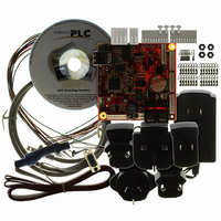
KIT EMBEDDED PLC APPLICATION
Manufacturer
Rabbit Semiconductor
Series
Coyoter
Type
MPU Moduler
Datasheet
1.101-1108.pdf
(70 pages)
Specifications of 101-1108
Contents
BL2500, ISaGRAF V3.50, Embedded PLC software kernel, ISaGRAF Programming Cable and Documentation
Processor To Be Evaluated
Rabbit 3000
Interface Type
RS-232, Ethernet
For Use With/related Products
BL2500
Lead Free Status / RoHS Status
Contains lead / RoHS non-compliant
Other names
316-1120


EMBEDDED
11. Select the Insert a Repeat-Until button
12. Select the flow link between the “Begin” symbol and the “End” symbol and delete it to allow for the
13. Click on the flow line connector that both the “LED_OFF” and the “LED_ON” action symbols connect
14. The FCtest1 Flow Chart should now appear as follows:
15. Save the program by selecting File menu → Save. Press OK button on the Update diary window.
16. Follow Steps 17 to 25 in 3.4.1 to compile and download it to the Target PLC.
17. Double-click on FCtest1 program. The FCTEST1 – Flow Chart window is displayed. Short circuit the
18. To stop the monitoring of the PLC application, close the Debugger window. The programs and
The ISaGRAF User’s Manual (See [2]) and the on-line help of the ISaGRAF Workbench describes in
detail all the Workbench functionalities (editor, simulation, debugger, etc.) including also a reference
manual of the PLC programming languages (IEC 61131-3).
OEM Technology Solutions
“SW1 = SW2” test symbol. Press Delete to just leave the flow line connector behind
program to run continuously without ending.
to. Select the Insert a flow button
symbols to the flow line connector remaining from Step 11. This allows the “SW1 = SW2” test to
repeat continuously, so if either of SW1 or SW2 change it can test again and change the LED1
output.
Close the FCtest1 – Flow Chart window.
digital input IN00 (SW1 will be FALSE), the LED1 will be turned ON as well as the state of LED1 in
the Programs window will change. The PLC program implements a Boolean XOR operation on SW1
and SW2 with the result set on the LED1.
dictionary windows in debug mode will be closed.
PLC BL2500 User’s Manual
and connect both the “LED_OFF” and the “LED_ON” action
and place it in between the “Begin” symbol and the
Running Sample Applications
.
Page 34
Related parts for 101-1108
Image
Part Number
Description
Manufacturer
Datasheet
Request
R

Part Number:
Description:
KIT DEV FOR BL2500 COYOTE
Manufacturer:
Rabbit Semiconductor
Datasheet:

Part Number:
Description:
KIT APPLICATION SIMPLE SENSOR
Manufacturer:
Rabbit Semiconductor
Datasheet:

Part Number:
Description:
KIT DEV RABBITCORE RCM3750
Manufacturer:
Rabbit Semiconductor
Datasheet:

Part Number:
Description:
KIT DEV RABBIT 2000 INT'L
Manufacturer:
Rabbit Semiconductor
Datasheet:
Part Number:
Description:
KIT DEV RABBIT RCM2000 INT'L
Manufacturer:
Rabbit Semiconductor
Datasheet:

Part Number:
Description:
KIT DEVELOPMENT RCM3700 INT'L
Manufacturer:
Rabbit Semiconductor
Datasheet:

Part Number:
Description:
BL4S200 TOOL KIT
Manufacturer:
Rabbit Semiconductor
Datasheet:


Part Number:
Description:
KIT DEVELOPMENT FOR JACKRABBIT
Manufacturer:
Rabbit Semiconductor
Part Number:
Description:
MODULE RABBITCORE RCM3720
Manufacturer:
Rabbit Semiconductor
Datasheet:
Part Number:
Description:
MODULE RABBITCORE RCM3220
Manufacturer:
Rabbit Semiconductor
Datasheet:
Part Number:
Description:
MODULE RABBITCORE RCM3210
Manufacturer:
Rabbit Semiconductor
Datasheet:
Part Number:
Description:
COMPUTER SGL-BOARD OP6600 W/SRAM
Manufacturer:
Rabbit Semiconductor
Datasheet:
Part Number:
Description:
COMPUTER SGL-BD BL2000 SRAM/FLSH
Manufacturer:
Rabbit Semiconductor