TOOLSTICK560DC Silicon Laboratories Inc, TOOLSTICK560DC Datasheet - Page 279
TOOLSTICK560DC
Manufacturer Part Number
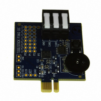
TOOLSTICK560DC
Description
DAUGHTER CARD TOOLSTICK F560
Manufacturer
Silicon Laboratories Inc
Series
ToolStickr
Type
MCUr
Specifications of TOOLSTICK560DC
Contents
Daughter Card
Processor To Be Evaluated
C8051F55x, C8051F56x, C8051F57x
Interface Type
USB
Operating Supply Voltage
2.7 V to 3.6 V
Lead Free Status / RoHS Status
Lead free / RoHS Compliant
For Use With/related Products
C8051F55x, C8051F56x, C8051F57x
For Use With
336-1345 - TOOLSTICK BASE ADAPTER336-1182 - ADAPTER USB DEBUG FOR C8051FXXX
Lead Free Status / Rohs Status
Lead free / RoHS Compliant
Other names
336-1719


26.2. PCA0 Interrupt Sources
Figure 26.3 shows a diagram of the PCA interrupt tree. There are five independent event flags that can be
used to generate a PCA0 interrupt. They are as follows: the main PCA counter overflow flag (CF), which is
set upon a 16-bit overflow of the PCA0 counter, an intermediate overflow flag (COVF), which can be set on
an overflow from the 8th, 9th, 10th, or 11th bit of the PCA0 counter, and the individual flags for each PCA
channel (CCF0, CCF1, CCF2, CCF3, CCF4, and CCF5), which are set according to the operation mode of
that module. These event flags are always set when the trigger condition occurs. Each of these flags can
be individually selected to generate a PCA0 interrupt, using the corresponding interrupt enable flag (ECF
for CF, ECOV for COVF, and ECCFn for each CCFn). PCA0 interrupts must be globally enabled before any
individual interrupt sources are recognized by the processor. PCA0 interrupts are globally enabled by set-
ting the EA bit and the EPCA0 bit to logic 1.
26.3. Capture/Compare Modules
Each module can be configured to operate independently in one of six operation modes: Edge-triggered
Capture, Software Timer, High Speed Output, Frequency Output, 8 to 11-Bit Pulse Width Modulator, or 16-
Bit Pulse Width Modulator. Each module has Special Function Registers (SFRs) associated with it in the
CIP-51 system controller. These registers are used to exchange data with a module and configure the
module's mode of operation. Table 26.2 summarizes the bit settings in the PCA0CPMn and PCA0PWM
registers used to select the PCA capture/compare module’s operating mode. All modules set to use 8, 9,
10, or 11-bit PWM mode must use the same cycle length (8-11 bits). Setting the ECCFn bit in a
PCA0CPMn register enables the module's CCFn interrupt.
PCA Counter/Timer 8, 9,
PCA Counter/Timer 16-
10 or 11-bit Overflow
bit Overflow
W
M
P
1
6
n
PCA Module 0
PCA Module 1
PCA Module 2
PCA Module 3
PCA Module 4
PCA Module 5
(for n = 0 to 2)
PCA0CPMn
C
O
M
E
n
C
A
P
P
(CCF0)
(CCF1)
(CCF2)
(CCF3)
(CCF4)
(CCF5)
n
C
A
P
N
n
M
A
T
n
O
G
T
n
W
P
M
n
E
C
C
F
n
C
F
C
R
PCA0CN
C
C
F
5
Figure 26.3. PCA Interrupt Block Diagram
C
C
F
4
C
C
F
3
C
C
F
2
C
C
F
1
C
C
F
0
ECCF0
ECCF1
ECCF2
ECCF3
ECCF4
ECCF5
C
D
L
I
W
D
T
E
PCA0MD
W
D
C
L
K
C
P
S
2
C
P
S
1
0
1
0
1
0
1
0
1
0
1
0
1
C
P
S
0
C
E
F
Rev. 1.1
0
1
A
R
S
E
L
PCA0PWM
C
O
V
F
C
O
E
V
0
1
C8051F55x/56x/57x
C
L
S
E
L
1
C
L
S
E
L
0
Set 8, 9, 10, or 11 bit Operation
EPCA0
0
1
EA
0
1
Interrupt
Priority
Decoder
279
Related parts for TOOLSTICK560DC
Image
Part Number
Description
Manufacturer
Datasheet
Request
R

Part Number:
Description:
KIT TOOL EVAL SYS IN A USB STICK
Manufacturer:
Silicon Laboratories Inc
Datasheet:

Part Number:
Description:
TOOLSTICK DEBUG ADAPTER
Manufacturer:
Silicon Laboratories Inc
Datasheet:

Part Number:
Description:
TOOLSTICK BASE ADAPTER
Manufacturer:
Silicon Laboratories Inc
Datasheet:

Part Number:
Description:
TOOLSTICK DAUGHTER CARD
Manufacturer:
Silicon Laboratories Inc
Datasheet:

Part Number:
Description:
TOOLSTICK DAUGHTER CARD
Manufacturer:
Silicon Laboratories Inc
Datasheet:

Part Number:
Description:
TOOLSTICK DAUGHTER CARD
Manufacturer:
Silicon Laboratories Inc
Datasheet:

Part Number:
Description:
TOOLSTICK PROGRAMMING ADAPTER
Manufacturer:
Silicon Laboratories Inc
Datasheet:

Part Number:
Description:
TOOLSTICK DAUGHTER CARD
Manufacturer:
Silicon Laboratories Inc
Datasheet:

Part Number:
Description:
KIT STARTER TOOLSTICK
Manufacturer:
Silicon Laboratories Inc
Datasheet:

Part Number:
Description:
KIT UNIVERSITY TOOLSTICK STARTER
Manufacturer:
Silicon Laboratories Inc
Datasheet:

Part Number:
Description:
DAUGHTER CARD TOOLSTICK F330
Manufacturer:
Silicon Laboratories Inc
Datasheet:

Part Number:
Description:
CARD DAUGHTER UNIVRSTY TOOLSTICK
Manufacturer:
Silicon Laboratories Inc
Datasheet:

Part Number:
Description:
DAUGHTER CARD TOOLSTICK F582
Manufacturer:
Silicon Laboratories Inc
Datasheet:

Part Number:
Description:
DAUGHTER CARD TOOLSTICK F500
Manufacturer:
Silicon Laboratories Inc
Datasheet:

Part Number:
Description:
DAUGHTER CARD TOOLSTICK F540
Manufacturer:
Silicon Laboratories Inc
Datasheet: