PMF18WE1 Microchip Technology, PMF18WE1 Datasheet - Page 48
PMF18WE1
Manufacturer Part Number
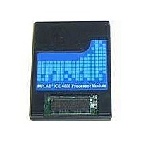
PMF18WE1
Description
PROCESSOR MODULE FOR ICE4000
Manufacturer
Microchip Technology
Datasheet
1.ICE4000.pdf
(98 pages)
Specifications of PMF18WE1
Module/board Type
Processor Module
Product
Microcontroller Modules
Core Processor
PIC18F6585/6680/8585/8680
Lead Free Status / RoHS Status
Contains lead / RoHS non-compliant
For Use With/related Products
ICE4000
Lead Free Status / RoHS Status
Lead free / RoHS Compliant, Contains lead / RoHS non-compliant


MPLAB
DS51490A-page 42
ICE 4000 User’s Guide
6.6.5
Figure 6-6 shows the Start Timer subtab of the Complex Trigger Settings tab for Time
Between Events selection. This event selection is used in conjunction with the trace
memory window.
1. Select Time Between Events to specify a starting and terminating event.
2. Click on a tab to enter information about:
FIGURE 6-6:
For the trigger type Time Between Events, the time stamp generator is held at zero until
a specified starting event occurs. The time stamp generator then continues to
increment normally until a specified stopping event occurs. The time stamp can then
be used to measure the lapsed time.
Up to two events and the start event can be specified to occur sequentially before the
time stamp generator starts incrementing. The trace memory display time stamp will
start incrementing when the starting event occurs and will stop when the terminating
event occurs. The time between the events can be determined by examining the time
stamp in the trace memory window.
- sequential events to proceed Start Timer (Event 1, Event 2)
- events for starting and stopping the timer (Start Timer, Stop Timer).
Time Between Events
1
COMPLEX TRIGGER – TIME BETWEEN EVENTS SELECTION
2
2004 Microchip Technology Inc.
Related parts for PMF18WE1
Image
Part Number
Description
Manufacturer
Datasheet
Request
R

Part Number:
Description:
Manufacturer:
Microchip Technology Inc.
Datasheet:
Part Number:
Description:
Manufacturer:
Microchip Technology Inc.
Datasheet:
Part Number:
Description:
Manufacturer:
Microchip Technology Inc.
Datasheet:
Part Number:
Description:
Manufacturer:
Microchip Technology Inc.
Datasheet:
Part Number:
Description:
Manufacturer:
Microchip Technology Inc.
Datasheet:
Part Number:
Description:
Manufacturer:
Microchip Technology Inc.
Datasheet:
Part Number:
Description:
Manufacturer:
Microchip Technology Inc.
Datasheet:
Part Number:
Description:
Manufacturer:
Microchip Technology Inc.
Datasheet: