PMF18WE1 Microchip Technology, PMF18WE1 Datasheet - Page 80
PMF18WE1
Manufacturer Part Number
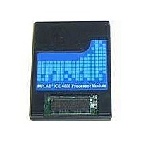
PMF18WE1
Description
PROCESSOR MODULE FOR ICE4000
Manufacturer
Microchip Technology
Datasheet
1.ICE4000.pdf
(98 pages)
Specifications of PMF18WE1
Module/board Type
Processor Module
Product
Microcontroller Modules
Core Processor
PIC18F6585/6680/8585/8680
Lead Free Status / RoHS Status
Contains lead / RoHS non-compliant
For Use With/related Products
ICE4000
Lead Free Status / RoHS Status
Lead free / RoHS Compliant, Contains lead / RoHS non-compliant


MPLAB
B.4
B.5
B.6
DS51490A-page 74
POWER
USB PORT
INDICATOR LIGHTS
ICE 4000 User’s Guide
Power to the MPLAB ICE 4000 system is supplied by an external power supply
included with the system. The input is located on the back of the pod, as indicated in
Figure B-1. The power on/off switch is also located on the back of the pod.
FIGURE B-1:
Power Supply Requirements:
+5V, ±5%, 0.75 A, and +3.3V, ±5%, 5.0 A
Power supplied by emulator: emulator loads system at 10 mA typical
Power supplied by target: emulator loads system at 80 mA typical
MPLAB ICE 4000 may be connected to the host PC via a universal serial bus (USB)
port, version 1.1 compliant. The USB connector is located on the rear panel of the pod
(Figure B-1). A USB port on the host PC is required.
Cable Length – The PC to MPLAB ICE 4000 cable length for proper operation has
been tested to be 6 feet. This length cable is shipped with MPLAB ICE 4000.
Four indicator lights are located on the front of the emulator (Figure B-2):
• Power LED – Green
• Status LED – Green
• Halt LED – Red
• Run LED – Green
Information about the indicator lights is detailed in the following sections.
FIGURE B-2:
Parallel Port
(Unused)
MPLAB ICE 4000 REAR VIEW
MPLAB ICE 4000 FRONT VIEW
Power
Communications
with PC
Host-to-Pod
USB
Indicator Lights
USB
Logic Probes
Connector
Processor Module
Connectors
Power Input
2004 Microchip Technology Inc.
Power On Power Off
I
O
Related parts for PMF18WE1
Image
Part Number
Description
Manufacturer
Datasheet
Request
R

Part Number:
Description:
Manufacturer:
Microchip Technology Inc.
Datasheet:
Part Number:
Description:
Manufacturer:
Microchip Technology Inc.
Datasheet:
Part Number:
Description:
Manufacturer:
Microchip Technology Inc.
Datasheet:
Part Number:
Description:
Manufacturer:
Microchip Technology Inc.
Datasheet:
Part Number:
Description:
Manufacturer:
Microchip Technology Inc.
Datasheet:
Part Number:
Description:
Manufacturer:
Microchip Technology Inc.
Datasheet:
Part Number:
Description:
Manufacturer:
Microchip Technology Inc.
Datasheet:
Part Number:
Description:
Manufacturer:
Microchip Technology Inc.
Datasheet: