PMF18WE1 Microchip Technology, PMF18WE1 Datasheet - Page 82
PMF18WE1
Manufacturer Part Number
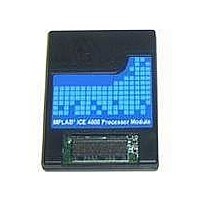
PMF18WE1
Description
PROCESSOR MODULE FOR ICE4000
Manufacturer
Microchip Technology
Datasheet
1.ICE4000.pdf
(98 pages)
Specifications of PMF18WE1
Module/board Type
Processor Module
Product
Microcontroller Modules
Core Processor
PIC18F6585/6680/8585/8680
Lead Free Status / RoHS Status
Contains lead / RoHS non-compliant
For Use With/related Products
ICE4000
Lead Free Status / RoHS Status
Lead free / RoHS Compliant, Contains lead / RoHS non-compliant


MPLAB
B.7
DS51490A-page 76
LOGIC PROBES
ICE 4000 User’s Guide
The 14-pin connector (Figure B-3) on the front panel of the MPLAB ICE 4000 emulator
(Figure B-2) provides power, ground, an external break input, a trigger input, a trigger
output and up to eight trace/trigger inputs.
FIGURE B-3:
Logic probes may be attached to this connector to give the functionality described in
Table B-1. The probes are color-coded for easy identification.
TABLE B-1:
The electrical specifications for logic probes are listed in Table B-2.
TABLE B-2:
Logic Inputs
Logic Outputs
TRGIN
TRGOUT
Pin
10
11
12
13
14
1
2
3
4
5
6
7
8
9
Gnd
Gnd
I/O
O
O
O
I
I
I
I
I
I
I
I
I
TRGOUT
HLTOUT
TRGIN
Name
LOGIC PROBE PINOUT DESCRIPTION
LOGIC PROBE ELECTRICAL SPECIFICATIONS
EXT7
EXT6
EXT5
EXT4
EXT3
EXT2
EXT1
EXT0
GND
GND
V
DD
LOGIC PROBE PINOUT
V
V
V
V
Minimum input pulse width = 15 nsec
The output pulse width of the filter trace is one bus cycle, which is ¼ the
clock speed (PICmicro MCU devices use four clocks for each
instruction).
IH
IL
OH
OL
= 1.8V max
= 3.2V min
= 0.4V max
= 2.4V min
System Power. Will supply +5V ±5%, up to 250 mA
Processor Halted Signal. Indicates whether the
processor is halted (high) or running (low).
Trigger/Break Out
Trigger In. Active-high input will freeze the trace
buffer without halting the processor or edge triggered
input will halt the processor.
External input bit 7 of the trace/trigger inputs.
External input bit 6 of the trace/trigger inputs.
External input bit 5 of the trace/trigger inputs.
External input bit 4 of the trace/trigger inputs.
External input bit 3 of the trace/trigger inputs.
External input bit 2 of the trace/trigger inputs.
External input bit 1 of the trace/trigger inputs.
External input bit 0 of the trace/trigger inputs.
System Ground
System Ground
Logic Probe Pinout on Emulator
13
14
Function
1
2
2004 Microchip Technology Inc.
Color
White
White
White
White
White
White
White
White
Black
Black
Gray
Gray
Gray
Red
Related parts for PMF18WE1
Image
Part Number
Description
Manufacturer
Datasheet
Request
R

Part Number:
Description:
Manufacturer:
Microchip Technology Inc.
Datasheet:
Part Number:
Description:
Manufacturer:
Microchip Technology Inc.
Datasheet:
Part Number:
Description:
Manufacturer:
Microchip Technology Inc.
Datasheet:
Part Number:
Description:
Manufacturer:
Microchip Technology Inc.
Datasheet:
Part Number:
Description:
Manufacturer:
Microchip Technology Inc.
Datasheet:
Part Number:
Description:
Manufacturer:
Microchip Technology Inc.
Datasheet:
Part Number:
Description:
Manufacturer:
Microchip Technology Inc.
Datasheet:
Part Number:
Description:
Manufacturer:
Microchip Technology Inc.
Datasheet: