PMF18WE1 Microchip Technology, PMF18WE1 Datasheet - Page 64
PMF18WE1
Manufacturer Part Number
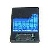
PMF18WE1
Description
PROCESSOR MODULE FOR ICE4000
Manufacturer
Microchip Technology
Datasheet
1.ICE4000.pdf
(98 pages)
Specifications of PMF18WE1
Module/board Type
Processor Module
Product
Microcontroller Modules
Core Processor
PIC18F6585/6680/8585/8680
Lead Free Status / RoHS Status
Contains lead / RoHS non-compliant
For Use With/related Products
ICE4000
Lead Free Status / RoHS Status
Lead free / RoHS Compliant, Contains lead / RoHS non-compliant


MPLAB
8.3
DS51490A-page 58
DEBUGGER MENU
ICE 4000 User’s Guide
The following items are added to the Debugger menu.
• Run
• Animate
• Halt
• Step Into
• Step Over
• Step Out
• Reset
• Breakpoints
• Stop Trace
Take the processor out of the halt state and put the processor into execution until
a breakpoint is encountered or until Halt is pressed.
Execution starts at the current program counter (as displayed in the status bar).
The current program counter location is also represented as a pointer in the
Program Memory window. While the processor is running, the Step and Run
buttons are disabled.
Continually Step Into instructions. Halt using Debugger>Halt.
Force the processor into the halt state. When you click Halt, the processor is
forced into a Halt state (Program Counter is stopped) and the processor status
information is updated.
Single step the processor. This command executes one processor instruction
(single or multiple cycle instructions) and then puts the processor back into halt
state. After execution of one instruction, all the windows are updated with the
current state of the processor. While the processor runs in real time, MPLAB IDE
ignores the Step button.
Execute the instruction at the current program counter location. At a call
instruction, Step Over executes the called subroutine and halts at the address
following the call.
Step out of current location in a function and return to main program.
Issue a reset sequence to the target processor, either Brown-Out Reset,
Power-On Reset, or Processor Reset. These reset the Program Counter to the
reset vector. If the processor is running it will continue running from the reset
vector address.
Open the Breakpoint dialog (Section 4.5 “Using Software Breakpoints”). Set
multiple software breakpoints in this dialog.
Halt the trace buffer (Chapter 7. “Code Coverage, Trace Memory, Real-Time
Reads”) from capturing data but allow the processor to continue running.
Note: Be careful about the instructions you are stepping into. If you step into a
Note: Reset will not currently wake the processor if it is in Sleep mode. To wake
Note: You may also right-click on a line of code to set a breakpoint.
Sleep instruction, you will need to select Debugger>Reinitialize ICE
Hardware in order to wake up the processor module.
the processor, you must use Debugger>Reinitialize ICE Hardware.
2004 Microchip Technology Inc.
Related parts for PMF18WE1
Image
Part Number
Description
Manufacturer
Datasheet
Request
R

Part Number:
Description:
Manufacturer:
Microchip Technology Inc.
Datasheet:
Part Number:
Description:
Manufacturer:
Microchip Technology Inc.
Datasheet:
Part Number:
Description:
Manufacturer:
Microchip Technology Inc.
Datasheet:
Part Number:
Description:
Manufacturer:
Microchip Technology Inc.
Datasheet:
Part Number:
Description:
Manufacturer:
Microchip Technology Inc.
Datasheet:
Part Number:
Description:
Manufacturer:
Microchip Technology Inc.
Datasheet:
Part Number:
Description:
Manufacturer:
Microchip Technology Inc.
Datasheet:
Part Number:
Description:
Manufacturer:
Microchip Technology Inc.
Datasheet: