EVAL-AD7856CB Analog Devices Inc, EVAL-AD7856CB Datasheet - Page 5
EVAL-AD7856CB
Manufacturer Part Number
EVAL-AD7856CB
Description
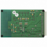
BOARD EVAL FOR AD7856
Manufacturer
Analog Devices Inc
Datasheet
1.AD7856ARSZ-REEL7.pdf
(32 pages)
Specifications of EVAL-AD7856CB
Lead Free Status / RoHS Status
Contains lead / RoHS non-compliant


REV. A
TYPICAL TIMING DIAGRAMS
Figures 2 and 3 show typical read and write timing diagrams for
serial Interface Mode 2. The reading and writing occurs after
conversion in Figure 2, and during conversion in Figure 3. To
attain the maximum sample rate of 285 kHz, reading and writ-
ing must be performed during conversion as in Figure 3. At
least 330 ns acquisition time must be allowed (the time from
the falling edge of BUSY to the next rising edge of CONVST)
before the next conversion begins to ensure that the part is
settled to the 14-bit level. If the user does not want to provide
the CONVST signal, the conversion can be initiated in software
by writing to the control register.
Figure 3. Timing Diagram for Interface Mode 2 (Reading/Writing During Conversion)
Figure 2. Timing Diagram for Interface Mode 2 (Reading/Writing After Conversion)
CONVST (I/P)
DOUT (O/P)
CONVST (I/P)
BUSY (O/P)
DOUT (O/P)
SYNC (I/P)
BUSY (O/P)
SCLK (I/P)
SYNC (I/P)
SCLK (I/P)
DIN (I/P)
DIN (I/P)
t
2
t
2
t
1
t
1
THREE-STATE
t
THREE-STATE
CONVERT
t
t
1
1
t
= 100ns MIN,
t
4
t
= 100ns MIN,
t
4
CONVERT
CONVERT
t
3
t
3
DB15
DB15
t
7
t
= 3.5 s MAX, 5.25 s MAX FOR K VERSION
7
1
= 3.5 s MAX, 5.25 s MAX FOR K VERSION
1
DB15
t
–5–
t
DB15
4
4
t
= 30/50ns MAX A/K,
= 30/50ns MAX A/K,
t
6
6
t
8
t
t
8
CONVERT
Figure 1. Load Circuit for Digital Output Timing
Specifications
DB11
DB11
5
5
DB11
DB11
t
t
t
7
t
6
7
t
t
9
6
= 30/40ns MIN A/K
TO OUTPUT
= 30/40ns MIN A/K
9
t
6
t
10
6
10
PIN
DB0
DB0
100pF
16
16
C
DB0
L
t
DB0
11
t
11
200 A
1.6mA
t
t
12
12
THREE-
STATE
THREE-
STATE
I
I
OL
OL
+2.1V
AD7856
Related parts for EVAL-AD7856CB
Image
Part Number
Description
Manufacturer
Datasheet
Request
R

Part Number:
Description:
ENERCHIP CC EVAL KIT
Manufacturer:
Cymbet Corporation
Datasheet:

Part Number:
Description:
BOARD EVAL FOR AD976
Manufacturer:
Analog Devices Inc
Datasheet:

Part Number:
Description:
BOARD EVAL FOR ADXL345
Manufacturer:
Analog Devices Inc
Datasheet:

Part Number:
Description:
ENERCHIP CC SEH EVAL KIT
Manufacturer:
Cymbet Corporation
Datasheet:

Part Number:
Description:
ENERCHIP EP ENERGY HARVEST EVAL
Manufacturer:
Cymbet Corporation
Datasheet:

Part Number:
Description:
EVAL BOARD FOR TW6864-LB2-GR
Manufacturer:
Intersil
Datasheet:
Part Number:
Description:
EVAL BOARD FOR TW8816-LB3-GR
Manufacturer:
Intersil
Datasheet:
Part Number:
Description:
EVAL BOARD FOR TW8817-TA3-GRS
Manufacturer:
Intersil
Datasheet:

Part Number:
Description:
EVALUATION MODULE FOR ADUM4160
Manufacturer:
Analog Devices Inc
Datasheet:

Part Number:
Description:
BOARD EVALUATION ADCMP581BCP
Manufacturer:
Analog Devices Inc
Datasheet:
Part Number:
Description:
BOARD EVALUATION ADM1041
Manufacturer:
Analog Devices Inc
Datasheet:

Part Number:
Description:
EVAL BOARD FOR STM32F107VCT
Manufacturer:
STMicroelectronics
Datasheet:
Part Number:
Description:
BOARD EVAL FOR AD1954
Manufacturer:
Analog Devices Inc
Datasheet:
Part Number:
Description:
BOARD EVAL FOR AD1955
Manufacturer:
Analog Devices Inc
Datasheet:

Part Number:
Description:
BOARD EVAL FOR AD7655
Manufacturer:
Analog Devices Inc
Datasheet: