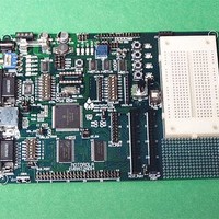
EVB9S12NE64 Freescale Semiconductor, EVB9S12NE64 Datasheet - Page 12

EVB9S12NE64
Manufacturer Part Number
EVB9S12NE64
Description
KIT EVALUATION FOR NE64
Manufacturer
Freescale Semiconductor
Datasheet
1.EVB9S12NE64.pdf
(20 pages)
Specifications of EVB9S12NE64
Mfg Application Notes
MC9S12NE64 Integrated Ethernet Controller Implementing an Ethernet Interface with the MC9S12NE64 Web Server Development with MC9S12NE64 and Open TCP
Processor To Be Evaluated
MC9S12NE64
Data Bus Width
16 bit
Interface Type
RS-232, Ethernet
Lead Free Status / RoHS Status
Contains lead / RoHS non-compliant
E V B 9 S 1 2 N E 6 4
FLOW_SEL Options
The FLOW_SEL option provides configuration of the RTS / CTS flow control signals to the
COM1 and COM2 port. FLOW Selection requires NE64 Port L5 to be enabled by the COM
Switch position 5 as the RTS output and NE64 Port G7 to be enabled by the COM Switch
position 6 as the NE64 board CTS input. User application software must also support the flow
control operation of RTS / CTS signaling on PTL5 and PTG7. Following are the 3 basic option
settings:
RTS signal active output level is logic 0. User should place port PTL5 at logic low (0) to enable
the RTS signal and reception of bytes if applied. User should apply a logic high signal under
software control inform host or connected RS232 device to STOP transmitting (stop sending
incoming bytes).
CTS signal active input level is logic 0. User should apply software to detect a logic high signal
on Port PTG7 and STOP transmitting bytes to the host or connected device to implement
hardware flow control. Detection of a logic low input indicates the host is ready to receive bytes
and the user (NE64) may transmit.
COM1
The COM1 port provides standard 9 pin connection with RS232 type interface to the HCS12
SCI0 peripheral. Refer to the COM_SW for enabling the HCS12 RXD0 and TXD0 signals
applied to this port. Refer to the COM_SW and FLOW_SEL options for enabling RTS/CTS flow
controls on this port. The COM1 port is applied by default with the embedded Monitor. HCS12
SCI0 TXD0 and RXD0 signals are converted to RS232 levels by U13 and provided to the
COM1 connector. The HCS12 PTL5 and PTG7 signals may be applied for the optional
RTS/CTS flow control on this port. Following is the DB9S connection reference.
COM1
FLOW_SEL with COM2 RTS / CTS enabled
RXD0 3 7 CTS IN
TXD0 2 6 6
FLOW_SEL Idle, no RTS / CTS
GND 5 9 9
1 1
4 4 8 RTS OUT
X
3
2
1
3
2
1
The COM-1 port is a Female (socket type) DB9 connector.
Pins 1, 4, and 6 connected for status null to host.
Pins 7 and 8 optioned by COM_SW and FLOW_SEL
FLOW_SEL with COM1 RTS / CTS enabled
12
0 5 / 2 4 / 0 4
3
2
1


