EVB9S12NE64 Freescale Semiconductor, EVB9S12NE64 Datasheet - Page 2
EVB9S12NE64
Manufacturer Part Number
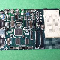
EVB9S12NE64
Description
KIT EVALUATION FOR NE64
Manufacturer
Freescale Semiconductor
Datasheet
1.EVB9S12NE64.pdf
(20 pages)
Specifications of EVB9S12NE64
Mfg Application Notes
MC9S12NE64 Integrated Ethernet Controller Implementing an Ethernet Interface with the MC9S12NE64 Web Server Development with MC9S12NE64 and Open TCP
Processor To Be Evaluated
MC9S12NE64
Data Bus Width
16 bit
Interface Type
RS-232, Ethernet
Lead Free Status / RoHS Status
Contains lead / RoHS non-compliant


E V B 9 S 1 2 N E 6 4
CAUTIONARY NOTES ...........................................................................................................................................................3
TERMINOLOGY ......................................................................................................................................................................3
FEATURES................................................................................................................................................................................4
GETTING STARTED...............................................................................................................................................................5
MONITOR OPERATION ........................................................................................................................................................6
EVB9S12NE64 OPERATION ..................................................................................................................................................7
M9S12NE64 PORT CONNECTORS ....................................................................................................................................17
TROUBLESHOOTING ............................................................................................................................................................19
S
R
EVB9S12NE64 S
MONITOR MEMORY MAP ..................................................................................................................................................6
RUN / LOAD S
MODE OPTIONS....................................................................................................................................................................7
POWER SUPPLY ...................................................................................................................................................................7
RESET O
OSC_SEL ................................................................................................................................................................................9
X1 CLOCK OSCILLATOR ....................................................................................................................................................9
EXTERNAL BUS .................................................................................................................................................................10
CONFIG S
J1 E
COM P
LCD PORT1
I2C EEPROM M
KEYPAD ...............................................................................................................................................................................15
USER COMPONENTS .........................................................................................................................................................15
BREADBOARD....................................................................................................................................................................16
MCU1_PORT........................................................................................................................................................................17
MCU2_GP PORT..................................................................................................................................................................18
BDM PORT...........................................................................................................................................................................18
PECIAL
EFERENCE
MODA, MODB, MODC ......................................................................................................................................................7
ROM_OFF...........................................................................................................................................................................7
MODE_CHART ...................................................................................................................................................................7
FUSE – FZ1.........................................................................................................................................................................8
Power Port...........................................................................................................................................................................8
Power Jack ..........................................................................................................................................................................8
PWR_SW – ON/OFF ...........................................................................................................................................................8
VRH_EN and VRL_EN ........................................................................................................................................................9
STATUS Indicators ............................................................................................................................................................11
COM_Switch......................................................................................................................................................................11
FLOW_SEL Options ..........................................................................................................................................................12
COM1 ................................................................................................................................................................................12
COM2 ................................................................................................................................................................................13
IRDA Port and JP3............................................................................................................................................................13
USER_ENABLE.................................................................................................................................................................15
USER_IO Connector .........................................................................................................................................................16
RV1 User Potentiometer ....................................................................................................................................................16
SW1 – SW4 Push Switches.................................................................................................................................................16
LED1 – 4 Indicators ..........................................................................................................................................................16
THERNET
ORTS
O
PERATION
PERATING
WITCH
D
...........................................................................................................................................................................11
P
AND
OCUMENTATION
ORT
WITCH
EMORY
...................................................................................................................................................................10
TARTUP
2 ...............................................................................................................................................................14
................................................................................................................................................................10
.................................................................................................................................................................9
N
OTES
.............................................................................................................................................................6
........................................................................................................................................................14
........................................................................................................................................................5
.....................................................................................................................................................5
.................................................................................................................................................5
CONTENTS
2
0 5 / 2 4 / 0 4
Related parts for EVB9S12NE64
Image
Part Number
Description
Manufacturer
Datasheet
Request
R

Part Number:
Description:
Manufacturer:
Freescale Semiconductor, Inc
Datasheet:
Part Number:
Description:
Manufacturer:
Freescale Semiconductor, Inc
Datasheet:
Part Number:
Description:
Manufacturer:
Freescale Semiconductor, Inc
Datasheet:
Part Number:
Description:
Manufacturer:
Freescale Semiconductor, Inc
Datasheet:
Part Number:
Description:
Manufacturer:
Freescale Semiconductor, Inc
Datasheet:
Part Number:
Description:
Manufacturer:
Freescale Semiconductor, Inc
Datasheet:
Part Number:
Description:
Manufacturer:
Freescale Semiconductor, Inc
Datasheet:
Part Number:
Description:
Manufacturer:
Freescale Semiconductor, Inc
Datasheet:
Part Number:
Description:
Manufacturer:
Freescale Semiconductor, Inc
Datasheet:
Part Number:
Description:
Manufacturer:
Freescale Semiconductor, Inc
Datasheet:
Part Number:
Description:
Manufacturer:
Freescale Semiconductor, Inc
Datasheet:
Part Number:
Description:
Manufacturer:
Freescale Semiconductor, Inc
Datasheet:
Part Number:
Description:
Manufacturer:
Freescale Semiconductor, Inc
Datasheet:
Part Number:
Description:
Manufacturer:
Freescale Semiconductor, Inc
Datasheet:
Part Number:
Description:
Manufacturer:
Freescale Semiconductor, Inc
Datasheet: