P2CF-08-E Omron, P2CF-08-E Datasheet - Page 8
P2CF-08-E
Manufacturer Part Number
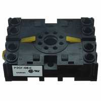
P2CF-08-E
Description
SOCKET 8-PIN FOR H3CR-H
Manufacturer
Omron
Type
Socketr
Specifications of P2CF-08-E
Number Of Positions
8
Mounting Type
DIN Rail
Termination Style
Screw Terminal
Size
70 mm x 50 mm x 19 mm
Socket Mounting
DIN Rail
Socket Terminals
Screw
Voltage Rating
240VAC
No. Of Pins
8
Accessory Type
Finger Safe Terminal
Rohs Compliant
Yes
Number Of Poles
8
Mounting Style
DIN Rail
For Use With/related Products
Multiple Series
For Use With
Z3000 - RELAY TIMER DGTL SPDT 12-24VDCZ2999 - RELAY TIMER DGTL SPDT 100/240VACH3CR-A8E AC100-240/DC100-125 - RELAY ANALOG SET DPDT 8PINZ2815 - RELAY REPEAT CYCLE ANALOG 30HRSZ2387 - RELAY TIMER 0-12SEC OFF-DELAYZ2386 - RELAY TIMER 0-12MIN OFF-DELAYZ2385 - RELAY REPEAT CYCLE ANALOG 30HRSZ2384 - RELAY REPEAT CYCLE ANALOG 300HRSZ2381 - RELAY ANALOG SET DPDT 8PINZ2380 - RELAY ANALOG SET DPDT 8PINZ2379 - RELAY ANALOG SET DPDT 8PINZ2382 - RELAY REPEAT CYCLE ANLG 30HRS
Lead Free Status / RoHS Status
Lead free / RoHS Compliant
Lead Free Status / RoHS Status
Lead free / RoHS Compliant, Lead free / RoHS Compliant
Other names
P2CF-08-E
P2CF08E
Z2836
P2CF08E
Z2836
Available stocks
Company
Part Number
Manufacturer
Quantity
Price
Company:

Part Number:
P2CF-08-E
Manufacturer:
Omron Electronics Inc-IA Div
Quantity:
135


■ Terminal Arrangement
Confirm that the power supply meets specifications before use.
Note 1. Do not connect unused terminals as relay terminals.
H5CX-A11/-A11D
H5CX-A/-AD
H5CX-L8/-L8D
The power supply and input circuit are not insulated.
(See note 2.)
Terminals 1 and 6 of the H5CX-AD are connected internally.
The power supply and input circuit of the
H5CX-A11 have basic insulation.
The power supply and input circuit of the
H5CX-A11D are not insulated. (See note 2.)
Terminals 2 and 3 of the H5CX-A11D are
connected internally.
The power supply and input circuit are
not insulated. (See note 2.)
Terminals 1 and 2 of the H5CX-L8D are
connected internally.
Input use 0 V
2. The power supply and input circuit are not insulated, so unwanted current from the AC power supply may burn out internal parts. Refer to
Signal
Reset
Reset
Signal
Gate
Safety Precautions (H5CX-A/-L) on page 49 for wiring details.
(−)
Unused
Unused
11
6
1
0 V
7
2
0 V
(+)
3
2
Unused
3
Unused
4
Contact output
2
12
(−)
4
1
8
3
5
(−)
1
6 7
(+)
11
5
8
(+)
9
4
Unused
10
6
7
8
Unused
9
10
13
5
Internal circuit
Internal circuit
Contact output
Contact output
The power supply and input circuit are not insulated.
(See note 2.)
Terminals 1 and 6 of the H5CX-ASD are connected internally.
The power supply and input circuit of the
H5CX-A11S have basic insulation.
The power supply and input circuit of the
H5CX-A11SD are not insulated. (See note 2.)
Terminals 2 and 3 of the H5CX-A11SD are
connected internally.
The power supply and input circuit are
not insulated. (See note 2.)
Terminals 1 and 2 of the H5CX-L8SD
are connected internally.
H5CX-A11S/-A11SD
H5CX-AS/-ASD
H5CX-L8S/-L8SD
Signal
Reset
Reset
Signal
Gate
Unused
Input use 0 V
0 V
(−)
0 V
Unused
3
2
11
3
Unused
6
1
4
2
(−)
5
4
1
(−)
1
7
2
6 7
(+)
(+)
11
(+)
5
8
Unused
Unused
Transistor output
10
12
6
7
8
3
8
9
9
4
Unused
Internal circuit
Internal circuit
Unused
10
13
5
Transistor output
Transistor output
H5CX-A/-L
8
Related parts for P2CF-08-E
Image
Part Number
Description
Manufacturer
Datasheet
Request
R

Part Number:
Description:
SOCKET 11-PIN FOR H3CR-H
Manufacturer:
Omron
Datasheet:

Part Number:
Description:
11 PIN Socket
Manufacturer:
Omron
Datasheet:

Part Number:
Description:
8 PIN Socket
Manufacturer:
Omron
Datasheet:

Part Number:
Description:
G6S-2GLow Signal Relay
Manufacturer:
Omron Corporation
Datasheet:
Part Number:
Description:
Compact, Low-cost, SSR Switching 5 to 20 A
Manufacturer:
Omron Corporation
Datasheet:
Part Number:
Description:
Manufacturer:
Omron Corporation
Datasheet:
Part Number:
Description:
Manufacturer:
Omron Corporation
Datasheet:
Part Number:
Description:
Manufacturer:
Omron Corporation
Datasheet:
Part Number:
Description:
Manufacturer:
Omron Corporation
Datasheet:
Part Number:
Description:
Manufacturer:
Omron Corporation
Datasheet: