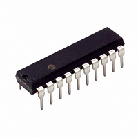
PIC16C770/P Microchip Technology, PIC16C770/P Datasheet - Page 45

PIC16C770/P
Manufacturer Part Number
PIC16C770/P
Description
IC MCU CMOS A/D 2K 20MHZ 20-DIP
Manufacturer
Microchip Technology
Series
PIC® 16Cr
Datasheets
1.PIC16C770-ISO.pdf
(220 pages)
2.PIC16C770-ISO.pdf
(6 pages)
3.PIC16C770-ISO.pdf
(8 pages)
Specifications of PIC16C770/P
Program Memory Type
OTP
Program Memory Size
3.5KB (2K x 14)
Package / Case
20-DIP (0.300", 7.62mm)
Core Processor
PIC
Core Size
8-Bit
Speed
20MHz
Connectivity
I²C, SPI
Peripherals
Brown-out Detect/Reset, POR, PWM, WDT
Number Of I /o
15
Ram Size
256 x 8
Voltage - Supply (vcc/vdd)
4 V ~ 5.5 V
Data Converters
A/D 6x12b
Oscillator Type
Internal
Operating Temperature
0°C ~ 70°C
Processor Series
PIC16C
Core
PIC
Data Bus Width
8 bit
Data Ram Size
256 B
Interface Type
I2C/SPI/SSP
Maximum Clock Frequency
20 MHz
Number Of Programmable I/os
16
Number Of Timers
3
Operating Supply Voltage
2.5 V to 5.5 V
Maximum Operating Temperature
+ 70 C
Mounting Style
Through Hole
3rd Party Development Tools
52715-96, 52716-328, 52717-734
Development Tools By Supplier
ICE2000
Minimum Operating Temperature
0 C
On-chip Adc
6-ch x 12-bit
Lead Free Status / RoHS Status
Lead free / RoHS Compliant
For Use With
DVA16XP200 - ADAPTER ICE 20DIP/SOIC/SSOPAC164028 - MODULE SKT PROMATEII 20SOIC/DIP
Eeprom Size
-
Lead Free Status / Rohs Status
Lead free / RoHS Compliant
- Current page: 45 of 220
- Download datasheet (4Mb)
4.3
To read a program memory location, the user must
write 2 bytes of the address to the PMADRH and
PMADRL
(PMCON1<0>). Once the read control bit is set, the
Program Memory Read (PMR) controller will use the
second instruction cycle after to read the data. This
causes the second instruction immediately following
EXAMPLE 4-1:
4.4
When the device is code protected, the CPU can still
perform the Program Memory Read function.
FIGURE 4-1:
2002 Microchip Technology Inc.
BSF
BCF
MOVLW
MOVWF
MOVLW
MOVWF
BSF
BSF
NOP
NOP
next instruction
PMDATH
PMDATL
Program
Memory
register
ADDR
RD bit
READING THE EPROM PROGRAM
MEMORY
OPERATION DURING CODE
PROTECT
registers,
STATUS, RP1
STATUS, RP0
MS_PROG_PM_ADDR
PMADRH
LS_PROG_PM_ADDR
PMADRL
STATUS, RP0
PMCON1, RD
Q1 Q2 Q3 Q4 Q1 Q2 Q3 Q4 Q1 Q2 Q3 Q4 Q1 Q2 Q3 Q4 Q1 Q2 Q3 Q4 Q1 Q2 Q3 Q4
PROGRAM MEMORY READ CYCLE EXECUTION
Executed here
INSTR(PC-1)
PC
OTP PROGRAM MEMORY Read
then
set
BSF PMCON1,RD
Executed here
;
; Bank 2
;
; MS Byte of Program Memory Address to read
;
; LS Byte of Program Memory Address to read
; Bank 3
; Program Memory Read
; This instruction must be an NOP
; This instruction must be an NOP
; PMDATH:PMDATL now has the data
control
PC+1
bit
PMADRH,PMADRL
RD
Executed here
INSTR(PC+1)
the “
is available, in the very next cycle, in the PMDATH and
PMDATL registers; therefore it can be read as 2 bytes
in the following instructions. PMDATH and PMDATL
registers will hold this value until another Program
Memory Read or until it is written to by the user.
Note:
PIC16C717/770/771
BSF PMCON1,RD
Executed here
Forced NOP
PC+3
PC+3
The two instructions that follow setting the
PMCON1 read bit must be NOPs.
” instruction to be ignored. The data
Executed here
INSTR(PC+3)
PC+4
DS41120B-page 43
Executed here
INSTR(PC+4)
PC+5
Related parts for PIC16C770/P
Image
Part Number
Description
Manufacturer
Datasheet
Request
R

Part Number:
Description:
IC, 8BIT MCU, PIC16C, 40MHZ, DIP-18
Manufacturer:
Microchip Technology
Datasheet:

Part Number:
Description:
IC, 8BIT MCU, PIC16C, 4MHZ, DIP-28
Manufacturer:
Microchip Technology
Datasheet:

Part Number:
Description:
IC, 8BIT MCU, PIC16C, 4MHZ, DIP-28
Manufacturer:
Microchip Technology
Datasheet:

Part Number:
Description:
IC, 8BIT MCU, PIC16C, 4MHZ, DIP-40
Manufacturer:
Microchip Technology
Datasheet:

Part Number:
Description:
SURFACE MOUNT POWER INDUCTORS
Manufacturer:
RCD [RCD COMPONENTS INC.]
Datasheet:

Part Number:
Description:
Manufacturer:
Microchip Technology Inc.
Datasheet:

Part Number:
Description:
Manufacturer:
Microchip Technology Inc.
Datasheet:

Part Number:
Description:
Manufacturer:
Microchip Technology Inc.
Datasheet:

Part Number:
Description:
Manufacturer:
Microchip Technology Inc.
Datasheet:

Part Number:
Description:
Manufacturer:
Microchip Technology Inc.
Datasheet:

Part Number:
Description:
Manufacturer:
Microchip Technology Inc.
Datasheet:


