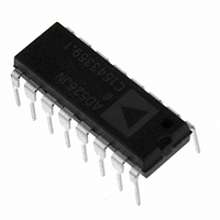
AD526JNZ Analog Devices Inc, AD526JNZ Datasheet - Page 12

AD526JNZ
Manufacturer Part Number
AD526JNZ
Description
IC AMP PGA 10MA 16DIP
Manufacturer
Analog Devices Inc
Type
Programmable Gain Amplifierr
Datasheet
1.AD526JNZ.pdf
(14 pages)
Specifications of AD526JNZ
Amplifier Type
Programmable Gain
Number Of Circuits
1
Slew Rate
24 V/µs
-3db Bandwidth
4MHz
Current - Input Bias
50pA
Voltage - Input Offset
400µV
Current - Supply
10mA
Current - Output / Channel
10mA
Voltage - Supply, Single/dual (±)
±4.5 V ~ 16.5 V
Operating Temperature
0°C ~ 70°C
Mounting Type
Through Hole
Package / Case
16-DIP (0.300", 7.62mm)
No. Of Amplifiers
1
Bandwidth
350kHz
No. Of Channels
1
Supply Voltage Range
± 4.5V To ± 16V
Amplifier Case Style
DIP
No. Of Pins
16
Operating Temperature Range
0°C To +70°C
Number Of Channels
1
Number Of Elements
1
Power Supply Requirement
Dual
Input Offset Voltage
1.5@±15VmV
Single Supply Voltage (typ)
Not RequiredV
Dual Supply Voltage (typ)
±5/±9/±12/±15V
Rail/rail I/o Type
No
Single Supply Voltage (min)
Not RequiredV
Single Supply Voltage (max)
Not RequiredV
Dual Supply Voltage (min)
±4.5V
Dual Supply Voltage (max)
±16.5V
Operating Temp Range
0C to 70C
Operating Temperature Classification
Commercial
Mounting
Through Hole
Pin Count
16
Package Type
PDIP
Lead Free Status / RoHS Status
Lead free / RoHS Compliant
Output Type
-
Gain Bandwidth Product
-
Lead Free Status / Rohs Status
Compliant
Available stocks
Company
Part Number
Manufacturer
Quantity
Price
AD526
FLOATING-POINT CONVERSION
High resolution converters are used in systems to obtain high
accuracy, improve system resolution or increase dynamic range.
There are a number of high resolution converters available with
throughput rates of 66.6 kHz that can be purchased as a single
component solution; however in order to achieve higher through-
put rates, alternative conversion techniques must be employed.
A floating point A/D converter can improve both throughput
rate and dynamic range of a system.
In a floating point A/D converter (Figure 42), the output data is
presented as a 16-bit word, the lower 12 bits from the A/D
converter form the mantissa and the upper 4 bits from the digi-
tal signal used to set the gain form the exponent. The AD526
programmable gain amplifier in conjunction with the compara-
tor circuit scales the input signal to a range between half scale
and full scale for the maximum usable resolution.
The A/D converter diagrammed in Figure 42 consists of a pair
of AD585 sample/hold amplifiers, a flash converter, a five-range
programmable gain amplifier (the AD526) and a fast 12-bit A/D
converter (the AD7572). The floating-point A/D converter
achieves its high throughput rate of 125 kHz by overlapping the
acquisition time of the first sample/hold amplifier and the set-
tling time of the AD526 with the conversion time of the A/D
converter. The first sample/hold amplifier holds the signal for
the flash autoranger, which determines which binary quantum
10 F
+
CLOCK
125MHz
+5V
1 F
–15V
AD588
+15V
1
V
1/6
IN
2
10 F
1.25k
1.25k
2.5k
+
10k
+5V
5k
10 F
3
+
1/6
REF
4
–15V
10k
AD585
S/H
LM339A
+15V
+5V
123
+5V
74-
1/2
10k
10k
10k
10k
+
10 F
30pF
10 F
+5V
10
1
2
4
5
9
74ALS86
50k
+
Figure 42. Floating-Point A/D Converter
1/4
1/4
1/4
1 s
11
V
B
A0 A1 A2
–15V
AD526
IN
3
6
8
+5V
1/6
+15V
12
13
1
2
10
F
S
1/4
1/4
+
10 F
11
3
10 F
+
–12–
–15V
the input falls within, relative to full scale. Once the AD526 has
settled to the appropriate level, then the second sample/hold
amplifier can be put into hold which holds the amplified signal
while the AD7572 perform its conversion routine. The acquisi-
tion time for the AD585 is 3 s, and the conversion time for the
AD7572 is 5 s for a total of 8 s, or 125 kHz. This performance
relies on the fast settling characteristics of the AD526 after the
flash autoranging (comparator) circuit quantizes the input sig-
nal. A 16-bit register holds the 3-bit output from the flash autor-
anger and the 12-bit output of the AD7572.
The A/D converter in Figure 42 has a dynamic range of 96 dB.
The dynamic range of a converter is the ratio of the full-scale
input range to the LSB value. With a floating-point A/D con-
verter the smallest value LSB corresponds to the LSB of the
monolithic converter divided by the maximum gain of the PGA.
The floating point A/D converter has a full-scale range of 5 V, a
maximum gain of 16 V/V from the AD526 and a 12-bit A/D
converter; this produces:
LSB = ([FSR/2
dynamic range in dBs is based on the log of the ratio of the
full-scale input range to the LSB; dynamic range = 20 log
(5 V/76 V) = 96 dB.
10k
AD585
A0
A1
A2
S/H
+15V
NOTE: ALL BYPASS CAPACITORS ARE 0.1 F
+
10 F
47 F
2.5MHz
N
10 F
68pF
68pF
]/Gain) = ([5 V/4096]/16) = 76 V. The
+
–15V
V
AD7572
IN
BUSY
MSB
+15V
LSB
+
10 F
5
1/6
6
LS174
LS174
LS174
74–
74–
74–
+5V
REV. D
D12
D11
D10
D9
D8
D7
D6
D5
D4
D3
D2
D1
E1
E2
E3


