EM250-BBRD-R Ember, EM250-BBRD-R Datasheet - Page 112
EM250-BBRD-R
Manufacturer Part Number
EM250-BBRD-R
Description
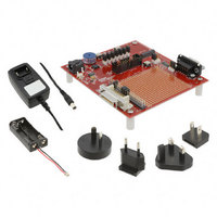
EM250 BREAKOUT BOARD
Manufacturer
Ember
Type
Transceiver, 802.15.4r
Datasheet
1.EM250-RCM-R.pdf
(126 pages)
Specifications of EM250-BBRD-R
Frequency
2.4GHz
For Use With/related Products
EM250
Lead Free Status / RoHS Status
Lead free / RoHS Compliant
Other names
636-1024


EM250
9 QFN48 Footprint Recommendations
120-0082-000S
Figure 20. Paste Mask Dimensions
Figure 19 demonstrates the IPC-7351 recommended PCB Footprint for the EM250 (QFN50P700X700X90-49N). A
ground pad in the bottom center of the package forms a 49
A 3 x 3 array of non-thermal vias should connect the EM250 decal center shown in Figure 19 to the PCB ground
plane through the ground pad. In order to properly solder the EM250 to the footprint, the Paste Mask layer
should have a 3 x 3 array of circular openings at 1.015mm diameter spaced approximately 1.625mm (center to
center) apart, as shown in Figure 20. This will cause an evenly distributed solder flow and coplanar attach-
ment to the PCB. The solder mask layer (illustrated in Figure 21) should be the same as the copper layer for
the EM250 footprint.
For more information on the package footprint, please refer to the EM250 Reference Design.
C2
b0
b2
a2
a0
b1
Figure 19. PCB Footprint for the EM250
a1
X2
C1
Page 112
X1
th
Figure 21. Solder Mask Dimensions
pin.
E
Y1
Via Drill DIA = 0.254mm
Y2
C1
C2
X1
X2
Y1
Y2
a0
a1
a2
b0
b1
b2
E
* Dimensions in mm
MIN
TYP
1.80
1.80
6.85
6.85
0.30
5.40
0.90
5.40
0.50
1.625
0.725
1.625
0.725
MAX
Related parts for EM250-BBRD-R
Image
Part Number
Description
Manufacturer
Datasheet
Request
R

Part Number:
Description:
IC ZIGBEE SYSTEM-ON-CHIP 48-QFN
Manufacturer:
Ember
Datasheet:

Part Number:
Description:
KIT JUMP START FOR EM250
Manufacturer:
Ember
Datasheet:

Part Number:
Description:
KIT EVAL EM250 RF TEST
Manufacturer:
Ember
Datasheet:

Part Number:
Description:
EM250 RCM BOARD
Manufacturer:
Ember
Datasheet:

Part Number:
Description:
KIT DEV FOR EM250
Manufacturer:
Ember
Datasheet:

Part Number:
Description:
KIT DEV EMBER ZIGBEE W/PCWH
Manufacturer:
Custom Computer Services Inc (CCS)

Part Number:
Description:
PROGRAMMER USB FLASH EM250/260
Manufacturer:
Ember
Datasheet:

Part Number:
Description:
IC ZIGBEE SYSTEM-ON-CHIP 40-QFN
Manufacturer:
Ember
Datasheet:
Part Number:
Description:
IC RF TXRX ZIGBEE 128KB 48QFN
Manufacturer:
Ember
Datasheet:
Part Number:
Description:
IC RF TXRX ZIGBEE 192KB 48QFN
Manufacturer:
Ember
Datasheet:

Part Number:
Description:
INSIGHT ADAPTER FOR EM2XX
Manufacturer:
Ember
Datasheet:

Part Number:
Description:
IAR EWARM LICENCE FOR EM35X
Manufacturer:
Ember
Datasheet:

Part Number:
Description:
INSIGHT ADAPTER 3 FOR EM35X
Manufacturer:
Ember
Datasheet:

Part Number:
Description:
EM35X BREAKOUT BOARD
Manufacturer:
Ember
Datasheet:

Part Number:
Description:
EM260 RCM BOARD
Manufacturer:
Ember
Datasheet: