101-1272 Rabbit Semiconductor, 101-1272 Datasheet - Page 97
101-1272
Manufacturer Part Number
101-1272
Description
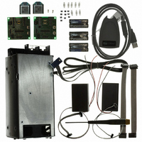
KIT MESH NETWORK ADD-ON RCM4510W
Manufacturer
Rabbit Semiconductor
Type
Microprocessorr
Datasheet
1.20-101-1207.pdf
(118 pages)
Specifications of 101-1272
Product
Modules
Data Bus Width
12 bit
Processor Type
Rabbit 4000
Sram
512 KB
Number Of I/os
20
Description/function
Computer Module
Interface Type
Ethernet
For Use With/related Products
RCM4510W
Lead Free Status / RoHS Status
Not applicable / Not applicable
Other names
316-1158


B.4.1 Adding Other Components
There are pads for 28-pin TSSOP devices, 16-pin SOIC devices, and 6-pin SOT devices
that can be used for surface-mount prototyping with these devices. There are also pads that
can be used for SMT resistors and capacitors in an 0805 SMT package. Each component
has every one of its pin pads connected to a hole in which a 30 AWG wire can be soldered
(standard wire wrap wire can be soldered in for point-to-point wiring on the Prototyping
Board). Because the traces are very thin, carefully determine which set of holes is con-
nected to which surface-mount pad.
B.4.2 Measuring Current Draw
The Prototyping Board has a current-measurement feature available at header locations
JP1 and JP2 for the +5 V and +3.3 V supplies respectively. To measure current, you will
have to cut the trace on the bottom side of the Prototyping Board corresponding to the
power supply or power supplies whose current draw you will be measuring. Header loca-
tions JP1 and JP2 are shown in Figure B-5. Then install a 1 × 2 header strip from the
Development Kit on the top side of the Prototyping Board at the header location(s) whose
trace(s) you cut. The header strip(s) will allow you to use an ammeter across their pins to
measure the current drawn from that supply. Once you are done measuring the current,
place a jumper across the header pins to resume normal operation.
User’s Manual
NOTE: Once you have cut the trace below header location JP1 or JP2, you must either be
using the ammeter or have a jumper in place in order for power to be delivered to the
Prototyping Board.
Figure B-5. Prototyping Board Current-Measurement Option
91
Related parts for 101-1272
Image
Part Number
Description
Manufacturer
Datasheet
Request
R

Part Number:
Description:
COMPUTER SNGLBD BL2120 FRCTNLOCK
Manufacturer:
Rabbit Semiconductor
Datasheet:

Part Number:
Description:
KIT APPLCTN RABBITCORE RCM4010
Manufacturer:
Rabbit Semiconductor
Datasheet:

Part Number:
Description:
KIT DEV FOR BL2500 COYOTE
Manufacturer:
Rabbit Semiconductor
Datasheet:

Part Number:
Description:
KIT APPLICATION SIMPLE SENSOR
Manufacturer:
Rabbit Semiconductor
Datasheet:

Part Number:
Description:
KIT DEV RCM5400W US/INTERNATIONL
Manufacturer:
Rabbit Semiconductor
Datasheet:

Part Number:
Description:
DEV KIT DELUXE MINICORE RCM5600W
Manufacturer:
Rabbit Semiconductor
Datasheet:


Part Number:
Description:
KIT FOR BL4S100 STARTER PACKAGE
Manufacturer:
Rabbit Semiconductor
Datasheet:

Part Number:
Description:
DEV KIT STANDARD MINI RCM5600W
Manufacturer:
Rabbit Semiconductor
Datasheet:

Part Number:
Description:
MODULE RABBITCORE RCM3720
Manufacturer:
Rabbit Semiconductor
Datasheet:
Part Number:
Description:
MODULE RABBITCORE RCM3220
Manufacturer:
Rabbit Semiconductor
Datasheet:
Part Number:
Description:
MODULE RABBITCORE RCM3210
Manufacturer:
Rabbit Semiconductor
Datasheet:
Part Number:
Description:
COMPUTER SGL-BOARD OP6600 W/SRAM
Manufacturer:
Rabbit Semiconductor
Datasheet:
Part Number:
Description:
COMPUTER SGL-BD BL2000 SRAM/FLSH
Manufacturer:
Rabbit Semiconductor