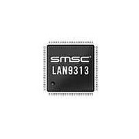
LAN9313-NZW SMSC, LAN9313-NZW Datasheet - Page 37

LAN9313-NZW
Manufacturer Part Number
LAN9313-NZW
Description
Ethernet ICs Three Port 10/100 Ethernet Switch
Manufacturer
SMSC
Type
Three Port Managed Ethernet Switchr
Datasheet
1.LAN9313-NZW.pdf
(399 pages)
Specifications of LAN9313-NZW
Ethernet Connection Type
10 Base-T, 100 Base-TX
Minimum Operating Temperature
0 C
Mounting Style
SMD/SMT
Product
Ethernet Switches
Number Of Transceivers
1
Standard Supported
802.3, 802.3u
Data Rate
10 Mbps, 100 Mbps
Supply Voltage (max)
3.6 V
Supply Voltage (min)
0 V
Supply Current (max)
155 mA, 270 mA
Maximum Operating Temperature
+ 70 C
Package / Case
TQFP-100
Lead Free Status / RoHS Status
Lead free / RoHS Compliant
Available stocks
Company
Part Number
Manufacturer
Quantity
Price
Company:
Part Number:
LAN9313-NZW
Manufacturer:
Microchip Technology
Quantity:
10 000
Part Number:
LAN9313-NZW
Manufacturer:
SMSC
Quantity:
20 000
- Current page: 37 of 399
- Download datasheet (5Mb)
Three Port 10/100 Managed Ethernet Switch with MII
Datasheet
SMSC LAN9313/LAN9313i
PIN
96
98
99
Note 3.9
Note 3.10 In MAC mode, this strap is not used. In this mode, the Virtual PHY is not applicable, and
EEPROM I
EEPROM I
Size Strap 1
Input/Output
Data Output
Serial Clock
Serial Clock
Serial Data
Type Strap
Data Input
EEPROM
Microwire
EEPROM
Microwire
EEPROM
EEPROM
Microwire
EEPROM
NAME
Configuration strap values are latched on power-on reset or nRST de-assertion.
Configuration strap pins are identified by an underlined symbol name. Some configuration
straps can be overridden by values from the EEPROM Loader. Refer to
"Configuration Straps," on page 45
full-duplex flow control must be controlled manually by the host, based upon the external
PHYs Auto-negotiation results.
2
2
C
C
EEPROM_TYPE
EEPROM_SIZE_1
SYMBOL
EE_SDA
EE_SCL
EECLK
EEDO
EEDI
Table 3.6 EEPROM Pins
DATASHEET
BUFFER
Note 3.11
Note 3.13
IS/OD8
IS/OD8
TYPE
(PD)
O8
O8
IS
IS
IS
37
for more information.
EEPROM Microwire Data Input (EEDI): In
Microwire EEPROM mode (EEPROM_TYPE = 0),
this pin is the Microwire EEPROM serial data input.
EEPROM I
(EE_SDA): In I
(EEPROM_TYPE = 1), this pin is the I
serial data input/output.
Note:
EEPROM Microwire Data Output: In Microwire
EEPROM mode (EEPROM_TYPE = 0), this pin is
the Microwire EEPROM serial data output.
Note:
Note:
EEPROM Type Strap: Configures the EEPROM
type. See
0 = Microwire Mode
1 = I
Note:
EEPROM Microwire Serial Clock (EECLK): In
Microwire EEPROM mode (EEPROM_TYPE = 0),
this pin is the Microwire EEPROM clock output.
EEPROM I
EEPROM mode (EEPROM_TYPE=1), this pin is
the I
Note:
EEPROM Size Strap 1: Configures the high bit of
the EEPROM size range as specified in
8.2, "I2C/Microwire Master EEPROM Controller,"
on page
EEPROMs. See
2
2
C EEPROM clock input/open-drain output.
C Mode
101. This bit is not used for I
If I
required when using an EEPROM and is
recommended if no EEPROM is attached.
In I
is not used and is driven low.
When not using a Microwire or I
EEPROM, an external pull-down resistor
is recommended on this pin.
When not using a Microwire or I
EEPROM, an external pull-down resistor
is recommended on this pin.
If I
required when using an EEPROM and is
recommended if no EEPROM is attached.
Note 3.12
2
2
2
2
C Serial Data Input/Output
C Serial Clock (EE_SCL): In I
2
C is selected, an external pull-up is
C is selected, an external pull-up is
C mode (EEPROM_TYPE=1), this pin
2
C EEPROM mode
Note
DESCRIPTION
3.12.
Revision 1.7 (06-29-10)
2
2
Section 4.2.4,
C EEPROM
C
Section
2
2
C
C
2
C
Related parts for LAN9313-NZW
Image
Part Number
Description
Manufacturer
Datasheet
Request
R

Part Number:
Description:
Ethernet ICs Three Port 10/100 Ethernet Switch
Manufacturer:
SMSC
Datasheet:

Part Number:
Description:
FAST ETHERNET PHYSICAL LAYER DEVICE
Manufacturer:
SMSC Corporation
Datasheet:

Part Number:
Description:
357-036-542-201 CARDEDGE 36POS DL .156 BLK LOPRO
Manufacturer:
SMSC Corporation
Datasheet:

Part Number:
Description:
357-036-542-201 CARDEDGE 36POS DL .156 BLK LOPRO
Manufacturer:
SMSC Corporation
Datasheet:

Part Number:
Description:
357-036-542-201 CARDEDGE 36POS DL .156 BLK LOPRO
Manufacturer:
SMSC Corporation
Datasheet:

Part Number:
Description:
4-PORT USB2.0 HUB CONTROLLER
Manufacturer:
SMSC Corporation
Datasheet:

Part Number:
Description:
Manufacturer:
SMSC Corporation
Datasheet:

Part Number:
Description:
Manufacturer:
SMSC Corporation
Datasheet:

Part Number:
Description:
FDC37C672ENHANCED SUPER I/O CONTROLLER WITH FAST IR
Manufacturer:
SMSC Corporation
Datasheet:

Part Number:
Description:
COM90C66LJPARCNET Controller/Transceiver with AT Interface and On-Chip RAM
Manufacturer:
SMSC Corporation
Datasheet:

Part Number:
Description:
Manufacturer:
SMSC Corporation
Datasheet:

Part Number:
Description:
Manufacturer:
SMSC Corporation
Datasheet:

Part Number:
Description:
Manufacturer:
SMSC Corporation
Datasheet:

Part Number:
Description:
Manufacturer:
SMSC Corporation
Datasheet:


