PIC24FV32KA304-I/PT Microchip Technology, PIC24FV32KA304-I/PT Datasheet - Page 210
PIC24FV32KA304-I/PT
Manufacturer Part Number
PIC24FV32KA304-I/PT
Description
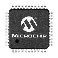
MCU 32KB FLASH 2KB RAM 44-TQFP
Manufacturer
Microchip Technology
Specifications of PIC24FV32KA304-I/PT
Processor Series
PIC24FV
Core
PIC
Data Bus Width
16 bit
Program Memory Type
Flash
Program Memory Size
32 KB
Data Ram Size
2 KB
Maximum Operating Temperature
+ 85 C
Mounting Style
SMD/SMT
Package / Case
TQFP-44
Development Tools By Supplier
MPLAB IDE Software
Minimum Operating Temperature
- 40 C
Lead Free Status / Rohs Status
Lead free / RoHS Compliant
Available stocks
Company
Part Number
Manufacturer
Quantity
Price
Company:

Part Number:
PIC24FV32KA304-I/PT
Manufacturer:
VISHAY
Quantity:
12 000
Company:
Part Number:
PIC24FV32KA304-I/PT
Manufacturer:
Microchip Technology
Quantity:
10 000


PIC24FV32KA304 FAMILY
REGISTER 21-1:
DS39995B-page 210
bit 15
bit 7
Legend:
R = Readable bit
-n = Value at POR
bit 15
bit 14
bit 13
bit 12-8
bit 7
bit 6
bit 5
bit 4
bit 3-0
Note 1:
HLVDEN
R/W-0
R/W-0
VDIR
For the actual trip point, see
HLVDEN: High/Low-Voltage Detect Power Enable bit
1 = HLVD is enabled
0 = HLVD is disabled
Unimplemented: Read as ‘0’
HLSIDL: HLVD Stop in Idle Mode bit
1 = Discontinue module operation when device enters Idle mode
0 = Continue module operation in Idle mode
Unimplemented: Read as ‘0’
VDIR: Voltage Change Direction Select bit
1 = Event occurs when voltage equals or exceeds trip point (HLVDL<3:0>)
0 = Event occurs when voltage equals or falls below trip point (HLVDL<3:0>)
BGVST: Band Gap Voltage Stable Flag bit
1 = Indicates that the band gap voltage is stable
0 = Indicates that the band gap voltage is unstable
IRVST: Internal Reference Voltage Stable Flag bit
1 = Indicates that the internal reference voltage is stable and the high-voltage detect logic generates
0 = Indicates that the internal reference voltage is unstable and the high-voltage detect logic will not
Unimplemented: Read as ‘0’
HLVDL<3:0>: High/Low-Voltage Detection Limit bits
1111 = External analog input is used (input comes from the HLVDIN pin)
1110 = Trip point 1
1101 = Trip point 2
1100 = Trip point 3
.
.
.
0000 = Trip point 15
BGVST
R/W-0
the interrupt flag at the specified voltage range
generate the interrupt flag at the specified voltage range, and the HLVD interrupt should not be
enabled
U-0
—
HLVDCON: HIGH/LOW-VOLTAGE DETECT CONTROL REGISTER
W = Writable bit
‘1’ = Bit is set
HLSIDL
R/W-0
R/W-0
IRVST
(1)
(1)
(1)
(1)
Section 29.0 “Electrical
U-0
U-0
—
—
U = Unimplemented bit, read as ‘0’
‘0’ = Bit is cleared
HLVDL3
R/W-0
U-0
—
Characteristics”.
HLVDL2
R/W-0
U-0
—
2011 Microchip Technology Inc.
x = Bit is unknown
HLVDL1
R/W-0
U-0
—
HLVDL0
R/W-0
U-0
—
bit 8
bit 0
Related parts for PIC24FV32KA304-I/PT
Image
Part Number
Description
Manufacturer
Datasheet
Request
R

Part Number:
Description:
Manufacturer:
Microchip Technology Inc.
Datasheet:
Part Number:
Description:
Manufacturer:
Microchip Technology Inc.
Datasheet:
Part Number:
Description:
Manufacturer:
Microchip Technology Inc.
Datasheet:
Part Number:
Description:
Manufacturer:
Microchip Technology Inc.
Datasheet:
Part Number:
Description:
Manufacturer:
Microchip Technology Inc.
Datasheet:
Part Number:
Description:
Manufacturer:
Microchip Technology Inc.
Datasheet:
Part Number:
Description:
Manufacturer:
Microchip Technology Inc.
Datasheet:
Part Number:
Description:
Manufacturer:
Microchip Technology Inc.
Datasheet: