LMH2190TM-38/NOPB National Semiconductor, LMH2190TM-38/NOPB Datasheet - Page 5
LMH2190TM-38/NOPB
Manufacturer Part Number
LMH2190TM-38/NOPB
Description
IC CLOCK QUAD 26MHZ DVR 16-USMD
Manufacturer
National Semiconductor
Type
Fanout Buffer (Distribution)r
Datasheet
1.LMH2190TM-38NOPB.pdf
(24 pages)
Specifications of LMH2190TM-38/NOPB
Number Of Circuits
1
Ratio - Input:output
1:4
Differential - Input:output
No/No
Input
Clock
Output
Clock
Frequency - Max
27MHz
Voltage - Supply
2.5 V ~ 5.5 V
Operating Temperature
-20°C ~ 85°C
Mounting Type
Surface Mount
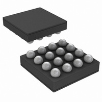
Package / Case
16-MicroSMD
Frequency-max
27MHz
Lead Free Status / RoHS Status
Lead free / RoHS Compliant
Other names
LMH2190TM-38TR
Available stocks
Company
Part Number
Manufacturer
Quantity
Price
Company:

Part Number:
LMH2190TM-38/NOPB
Manufacturer:
NS
Quantity:
270


PSRR
E
T
ΔV
R
T
SHTDWN
ON
Symbol
N
OUT
Note 1: Absolute Maximum Ratings indicate limits beyond which damage to the device may occur. Operating Ratings indicate conditions for which the device is
intended to be functional, but specific performance is not guaranteed. For guaranteed specifications and the test conditions, see the Electrical Characteristics
Tables.
Note 2: Human body model, applicable std. MIL-STD-883, Method 3015.7. Machine model, applicable std. JESD22–A115–A (ESD MM std of JEDEC). Field-
Induced Charge-Device Model, applicable std. JESD22–C101–C. (ESD FICDM std. of JEDEC)
Note 3: The maximum power dissipation is a function of T
P
Note 4: Electrical Table values apply only for factory testing conditions at the temperature indicated. Factory testing conditions result in very limited self-heating
of the device such that T
T
Note 5: Typical values represent the most likely parametric norm as determined at the time of characterization. Actual typical values may vary over time and will
also depend on the application and configuration. The typical values are not tested and are not guaranteed on shipped production material.
Note 6: Limits are 100% production tested at 25°C. Limits over temperature range are guaranteed through correlations using statistical quality control (SQC)
method.
Note 7: This parameter is guaranteed by design and/or characterization and is not tested in production.
Note 8: I
Note 9: V
Note 10: I
Note 11: C
Note 12: The device maintains stable, regulated output voltage without a load.
Note 13: Appropriate output load register must be set.
Note 14: Dropout voltage is the voltage difference between the supply voltage and the output voltage at which the output voltage drops to 100 mV below its
nominal value.
OUT
D
J
> T
= (T
A
.
J(MAX)
DD
DD_IO
2
C interface uses IO cells guaranteed for 1.8V typical supply (1.6V Min - 2.0V Max).
BAT
current depends on switching frequency and load.
Power Supply Rejection Ratio
Output Noise Voltage
Thermal Shutdown
Line Transient
Load Transient
Overshoot on Startup
DC Output Resistance
Turn on Time
- T
, C
is equal to V
A
)/θ
OUT
JA
: Low-ESR Surface-Mount Ceramic Capacitors (MLCCs) used in setting electrical characteristics.
. All numbers apply for packages soldered directly onto a PC board.
J
Parameter
= T
OUT
A
(Note
. No guarantee of parametric performance is indicated in the electrical tables under conditions of internal self-heating where
(Note
(Note
when the LDO is enabled and it is equal to V
7)
7)
7)
(Note
7)
V
I
BW = 10Hz to 100 kHz, V
C
Temperature
Hysteresis
V
(NOM)
V
(NOM)
I
I
to 95% of V
OUT
OUT
OUT
BAT
OUT
BAT
BAT
J(MAX)
= 10 mA
= 0 mA to 10 mA in 10 µs
= 10 mA to 0 mA in 10 µs
ripple = 200 mV
= (V
= (V
+ 1.6V) in 30 µs
+ 1.0V) in 30 µs
= 2.2 µF, All Outputs are Off
, θ
JA
OUT (NOM)
OUT (NOM)
and T
OUT (NOM)
Condition
A
. The maximum allowable power dissipation at any ambient temperature is
ENABLE
+ 1.0V) to (V
+ 1.6V) to (V
5
PP
when it is disabled.
,
f = 100 Hz
f = 217.5 Hz
f = 1 kHz
f = 10 kHz
f = 50 kHz
f = 100 kHz
f = 1 MHz
f = 3.25 MHz
BAT
= 4.2V,
OUT
OUT
(Note
Min
-70
-1
6)
(Note
Typ
160
185
93
90
78
62
54
50
42
35
10
20
5
5)
(Note
Max
100
270
30
1
6)
www.national.com
µV
Units
mV
mV
mV
dB
°C
µs
Ω
RMS
Related parts for LMH2190TM-38/NOPB
Image
Part Number
Description
Manufacturer
Datasheet
Request
R

Part Number:
Description:
Quad Channel 27 MHz Clock Tree Driver with I2C Interface
Manufacturer:
NSC [National Semiconductor]
Datasheet:
Part Number:
Description:
Lmh2190 Quad Channel 27 Mhz Clock Tree Driver With I2c Interface
Manufacturer:
National Semiconductor Corporation
Datasheet:

Part Number:
Description:
National Semiconductor [8-Bit D/A Converter]
Manufacturer:
National Semiconductor
Datasheet:
Part Number:
Description:
National Semiconductor [Media Coprocessor]
Manufacturer:
National Semiconductor
Datasheet:
Part Number:
Description:
Digitally Controlled Tone and Volume Circuit with Stereo Audio Power Amplifier, Microphone Preamp Stage and National 3D Sound
Manufacturer:
National Semiconductor
Datasheet:
Part Number:
Description:
Digitally Controlled Tone and Volume Circuit with Stereo Audio Power Amplifier, Microphone Preamp Stage and National 3D Sound
Manufacturer:
National Semiconductor
Datasheet:
Part Number:
Description:
AC97 Rev 2 Codec with Sample Rate Conversion and National 3D Sound
Manufacturer:
National Semiconductor
Part Number:
Description:
Manufacturer:
National Semiconductor
Datasheet:
Part Number:
Description:
Manufacturer:
National Semiconductor
Datasheet:
Part Number:
Description:
General Purpose, Low Voltage, Low Power, Rail-to-Rail Output Operational Amplifiers
Manufacturer:
National Semiconductor
Datasheet:
Part Number:
Description:
8-bit 20 MSPS flash A/D converter.
Manufacturer:
National Semiconductor
Datasheet:
Part Number:
Description:
Low Noise Quad Operational Amplifier
Manufacturer:
National Semiconductor
Datasheet:
Part Number:
Description:
Quad Differential Line Receivers
Manufacturer:
National Semiconductor
Datasheet:
Part Number:
Description:
Quad High Speed Trapezoidal? Bus Transceiver
Manufacturer:
National Semiconductor
Datasheet: