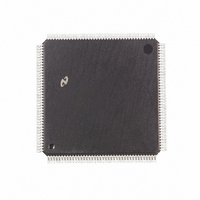
DP83953VUL National Semiconductor, DP83953VUL Datasheet - Page 75

DP83953VUL
Manufacturer Part Number
DP83953VUL
Description
IC CTRLR RIC REPEATER 160-PQFP
Manufacturer
National Semiconductor
Datasheet
1.DP83953VUL.pdf
(90 pages)
Specifications of DP83953VUL
Controller Type
Ethernet Repeater Interface Controller
Interface
IEEE 802.3
Voltage - Supply
4.75 V ~ 5.25 V
Current - Supply
870mA
Operating Temperature
0°C ~ 70°C
Mounting Type
Surface Mount
Package / Case
160-MQFP, 160-PQFP
Lead Free Status / RoHS Status
Contains lead / RoHS non-compliant
Other names
*DP83953VUL
Available stocks
Company
Part Number
Manufacturer
Quantity
Price
Company:
Part Number:
DP83953VUL
Manufacturer:
HJC
Quantity:
2 010
Company:
Part Number:
DP83953VUL
Manufacturer:
Texas Instruments
Quantity:
10 000
8.0 Board Layout Recommendations
There are numerous methods to layout PCB boards to
achieve successful proper operation. Two options for the
RIC2A layout are presented here. These NSC recommen-
dations have not been empirically proven in the laboratory.
Power and Ground Planes
Standard analog design techniques should be utilized
when laying out the power supply traces on the board. If a
digital power supply is used, NSC recommends a one pole
RC filter designed with a cut-off frequency of 1 kHz to
improve the signal jitter performance. See the figure below
This methodology facilitates locking of the PLL when cap-
turing the incoming signal. This filtering scheme should be
implemented on each of the analog power and ground pins
(
tionally, NSC recommends ferrite chokes to isolate the vari-
ous ground signals.
Power Plane
The power plane should be divided into distinct islands to
reduce and isolate noise effects. The signal traces which
traverse across multiple islands should be minimized and
impedance matched to reduce standing wave reflections.
The power plane for the device may be divided into three
regions as shown in the figure: Digital
PLL
bining the Analog and PLL
ing the Digital
ferrite beads to isolate the Digital
regions
Ground Plane
Option 1: The ground plane is one single uniform plane.
Option 2: The ground plane for the RIC2A is divided into
islands to minimize the effects of noise. The signal traces
which traverse across multiple islands should be minimized
and impedance matched to reduce standing wave reflec-
tions.
The ground plane for the device may be divided into three
regions as shown in the figure: Digital GND, Analog GND
and PLL GND. Or, it can be divided in only two regions: by
combining the Analog and PLL GND regions into one, and
leave the Digital GND as a separate region. NSC recom-
mends a ferrite bead between the Digital GND (Board
GND) and Analog GND regions for isolation.
The ground pin on the external 40 MHz oscillator should be
connected to the RIC2A's digital ground region. (The out-
V
DD
A, GNDA,
V
DD
. Or, it may be divided in only two regions: by com-
Figure 22. Recommended RC Filter
V
V
DD
DD
PLL, GNDPLL,
as a separate region. NSC recommends
V
DD
regions into one, and leav-
V
DD
V
WS, GNDWS). Addi-
V
DD
DD
, Analog
and Analog
V
DD
and
V
DD
75
put of the oscillator will be connected to RIC2A's CLKIN
signal, pin 100.)
All the port ground pins on the RIC2A should be connected
to the digital ground region. If only two regions are created,
the GNDPLL, GNDWS, and GNDA pins on the RIC2A
should be connected to the analog ground region.
Device Layout
Due to high device power dissipation, additional layout con-
siderations should be applied to ease that process. Placing
an additional metal layer right below the device placement
(on the component layer) will sink additional current into the
ground plane and will aid in cooling the device. See
Figure 25. The metal traces should be placed between the
last corner pins on both sides. Make the traces as thick as
possible. Multiple vias to ground should be placed on these
metal traces (and as many as layout will allow).
The RIC2A Airflow Fan
For a RIC2A design, a fan is recommended to increase air-
flow and keep junction temperature down.
Decoupling Capacitors
National strongly recommends decoupling capacitors
between the power and ground pins. See Figure 26 below
for specific placement and value.
Figure 23. The RIC2A Power Plane is Divided into
Islands to Reduce and Isolate Noise Effects
www.national.com


