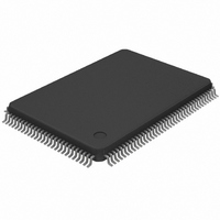
DS21448L+ Maxim Integrated Products, DS21448L+ Datasheet - Page 26

DS21448L+
Manufacturer Part Number
DS21448L+
Description
IC LIU QUAD E1/T1/J1 128-LQFP
Manufacturer
Maxim Integrated Products
Type
Line Interface Units (LIUs)r
Datasheet
1.DS21448L.pdf
(60 pages)
Specifications of DS21448L+
Number Of Drivers/receivers
4/4
Protocol
T1/E1/J1
Voltage - Supply
3.135 V ~ 3.465 V
Mounting Type
Surface Mount
Package / Case
128-TQFP, 128-VQFP
Product
Framer
Number Of Transceivers
4
Supply Voltage (max)
3.465 V
Supply Voltage (min)
3.135 V
Supply Current (max)
400 mA
Maximum Operating Temperature
+ 70 C
Minimum Operating Temperature
0 C
Mounting Style
SMD/SMT
Lead Free Status / RoHS Status
Lead free / RoHS Compliant
RIR1 (08H): Receive Information Register 1
RIR2 (09H): Receive Information Register 2
(Real Time)
(Real Time)
(Real Time)
(Real Time)
(Real Time)
(Latched)
(Latched)
(Latched)
(Latched)
(Latched)
(Latched)
(latched)
(MSB)
(MSB)
RUA1C
NAME
NAME
RCLC
ARLB
RL3
16ZD
JALT
HBD
ZD
SEC
RL3
RL2
RL1
RL0
N/A
N/A
N/A
N/A
ZD
POSITION
POSITION
16ZD
RL2
RIR1.1
RIR1.0
RIR2.3
RIR2.2
RIR1.7
RIR1.6
RIR1.5
RIR1.4
RIR1.3
RIR1.2
RIR2.7
RIR2.6
RIR2.5
RIR2.4
RIR2.1
RIR2.0
Zero Detect. This bit is set when a string of at least four (ETS = 0) or eight (ETS = 1)
consecutive 0s (regardless of the length of the string) have been received. This bit is cleared
when read.
16 Zero Detect. This is set when at least 16 consecutive 0s (regardless of the length of the
string) have been received. This bit is cleared when read.
HDB3/B8ZS Word Detect. This is set when an HDB3 (ETS = 0) or B8ZS (ETS = 1) codeword
is detected independently of the receive HDB3/B8ZS mode (CCR4.6) being enabled. This bit
is cleared when read. It is useful for automatically setting the line coding.
RCL Clear. Set when the RCL alarm has met the clear criteria defined in
is cleared when read.
Receive Unframed All-Ones Clear. This bit is set when the unframed all-ones signal is no
longer detected. This bit is cleared when read
Jitter Attenuator Limit Trip. This bit is set when the jitter attenuator FIFO reaches within 4 bits
of its useful limit. This bit is cleared when read and is useful for debugging jitter attenuation
operation.
Not Assigned. Could be any value when read.
Not Assigned. Could be any value when read.
Receive Level Bit 3
Receive Level Bit 2
Receive Level Bit 1
Receive Level Bit 0
Not Assigned. Could be any value when read.
Not Assigned. Could be any value when read.
Automatic Remote Loopback Detected. This bit is set to 1 when the automatic remote
loopback circuitry has detected the presence of a loop-up code for 5 seconds. It remains set
until the automatic RLB circuitry has detected the loop-down code for 5 seconds. See
Section
disabled (CCR6.5 = 0).
One-Second Timer. This bit is set to 1 on one-second boundaries as timed by the device,
based on the RCLK. It is cleared when read.
HBD
RL1
11
for more details. This bit is forced low when the automatic RLB circuitry is
RCLC
RL0
(Table
(Table
(Table
(Table
26 of 60
5-B)
5-B)
5-B)
5-B)
RUA1C
—
FUNCTION
FUNCTION
(Table
JALT
—
5-A).
ARLB
—
Table
5-A. This bit
(LSB)
(LSB)
SEC
—


