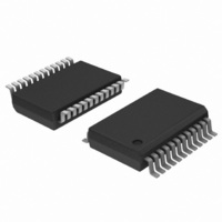
TDA9884TS/V1,112 NXP Semiconductors, TDA9884TS/V1,112 Datasheet - Page 25

TDA9884TS/V1,112
Manufacturer Part Number
TDA9884TS/V1,112
Description
IC IF-PLL I2C-BUS DEMOD 24-SSOP
Manufacturer
NXP Semiconductors
Type
Demodulatorr
Datasheet
1.TDA9884TSV1112.pdf
(58 pages)
Specifications of TDA9884TS/V1,112
Package / Case
*
Applications
Mobile Reception
Mounting Type
Surface Mount
Maximum Operating Temperature
+ 70 C
Minimum Operating Temperature
- 20 C
Mounting Style
SMD/SMT
Lead Free Status / RoHS Status
Lead free / RoHS Compliant
Other names
935270308112
TDA9884TS/V1
TDA9884TS/V1
TDA9884TS/V1
TDA9884TS/V1
Philips Semiconductors
Table 25.
V
f
IF input from 50
video signal in accordance with “ITU-T J.63 line 17 and line 330” or “NTC-7 Composite”; measurements taken in test circuit of
Figure
TDA9884_2
Product data sheet
Symbol
t
D/K standard; see
B
t
Video output 1.1 V (pin CVBS)
Trap bypass mode and sound carrier off
V
V
V
V
B
B
S/N
S/N
SC
d(g)(cc)
d(g)(cc)
P
SC1(60kHz)
SC2
SC2(60kHz)
SC1
SC1(60kHz)
SC2
SC2(60kHz)
v( 3dB)(trap)
o(v)(p-p)
sync
clip(u)
clip(l)
v( 1dB)
v( 3dB)
= 5 V; T
= 33.4 MHz; PC/SC = 13 dB; f
W
UW
23; unless otherwise specified.
amb
Characteristics
= 25 C; see
via broadband transformer 1 : 1; video modulation DSB; residual carrier for B/G is 10 % and for L is 3 %;
Figure 21
Parameter
attenuation at first
sound carrier
f
attenuation at
second sound carrier
attenuation at
second sound carrier
f
group delay at color
carrier frequency
bandwidth including
sound carrier trap
attenuation at first
sound carrier
attenuation at first
sound carrier
f
attenuation at
second sound carrier
attenuation at
second sound carrier
f
group delay at color
carrier frequency
video output voltage
(peak-to-peak value)
sync voltage level
upper video clipping
voltage level
lower video clipping
voltage level
bandwidth
bandwidth
weighted
signal-to-noise ratio
unweighted
signal-to-noise ratio
SC1
SC2
SC1
SC2
3 dB video
1 dB video
3 dB video
Table 27
60 kHz
60 kHz
60 kHz
60 kHz
…continued
mod
for input frequencies; B/G standard is used for the specification (f
= 400 Hz); input level V
[14]
Conditions
f = 6.0 MHz
f = 6.55 MHz
f = 6.55 MHz
f = 4.43 MHz
f
f = 6.5 MHz
f = 6.5 MHz
f = 6.742 MHz
f = 6.742 MHz
f = 4.28 MHz
see
AC load; C
R
AC load; C
R
Figure 5
trap
L
L
> 1 k
> 1 k
= 6.5 MHz
Figure 9
Rev. 02 — 12 May 2006
L
L
< 20 pF;
< 20 pF;
I
2
C-bus controlled multistandard alignment-free IF-PLL
i(VIF)
= 10 mV (RMS) (sync level for B/G; peak white level for L);
[13]
[8]
[9]
Min
20
12
10
-
5.50
26
20
18
13
-
0.95
1.35
3.5
-
5
7
56
48
© Koninklijke Philips Electronics N.V. 2006. All rights reserved.
Typ
26
18
15
90
5.95
32
26
24
18
60
1.10
1.5
3.6
0.9
6
8
59
52
PC
TDA9884
Max
-
-
-
160
-
-
-
-
-
130
1.25
1.6
-
1.0
-
-
-
-
= 38.9 MHz;
Unit
dB
dB
dB
ns
MHz
dB
dB
dB
dB
ns
V
V
V
V
MHz
MHz
dB
dB
25 of 58


