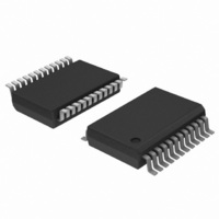
TDA9884TS/V1,112 NXP Semiconductors, TDA9884TS/V1,112 Datasheet - Page 35

TDA9884TS/V1,112
Manufacturer Part Number
TDA9884TS/V1,112
Description
IC IF-PLL I2C-BUS DEMOD 24-SSOP
Manufacturer
NXP Semiconductors
Type
Demodulatorr
Datasheet
1.TDA9884TSV1112.pdf
(58 pages)
Specifications of TDA9884TS/V1,112
Package / Case
*
Applications
Mobile Reception
Mounting Type
Surface Mount
Maximum Operating Temperature
+ 70 C
Minimum Operating Temperature
- 20 C
Mounting Style
SMD/SMT
Lead Free Status / RoHS Status
Lead free / RoHS Compliant
Other names
935270308112
TDA9884TS/V1
TDA9884TS/V1
TDA9884TS/V1
TDA9884TS/V1
Philips Semiconductors
Table 25.
V
f
IF input from 50
video signal in accordance with “ITU-T J.63 line 17 and line 330” or “NTC-7 Composite”; measurements taken in test circuit of
Figure
[1]
[2]
[3]
[4]
TDA9884_2
Product data sheet
Symbol
V
R
C
I
f
V
V
I
I
V
I
I
Output ports (pins OP1 and OP2)
V
V
I
I
SC
2
SCL
IH
IL
o(sink)
o(source)
o(sink)
o(sink/source)(max)
P
ref(rms)
C-bus transceiver (pins SDA and SCL)
IH
IL
OL
OL
OH
o(ref)
K
= 5 V; T
= 33.4 MHz; PC/SC = 13 dB; f
Values of video and sound parameters can be decreased at V
For applications without I
Level headroom for input level jumps during gain control setting.
This parameter is not tested during the production and is only given as application information for designing the receiver circuit.
23; unless otherwise specified.
amb
Characteristics
= 25 C; see
via broadband transformer 1 : 1; video modulation DSB; residual carrier for B/G is 10 % and for L is 3 %;
Parameter
reference signal
voltage (RMS value)
output resistance of
reference signal
source
decoupling
capacitance to
external reference
signal source
SCL clock frequency
HIGH-level input
voltage
LOW-level input
voltage
HIGH-level input
current
LOW-level input
current
LOW-level output
voltage
output sink current
output source
current
LOW-level output
voltage
HIGH-level output
voltage
output sink current
maximum output
sink or source
current
2
C-bus, the time constant (R
Table 27
…continued
mod
[15][19][38]
for input frequencies; B/G standard is used for the specification (f
= 400 Hz); input level V
[36][37]
Conditions
operation as input terminal
operation as input terminal
I
V
V
I
pin OP2 functions as
VIF-AGC output
OL
OL
P
P
= 0 V
= 0 V
= 3 mA
= 2 mA (sink current)
Rev. 02 — 12 May 2006
C) at the supply must be > 1.2 s (e.g. 1
I
P
2
C-bus controlled multistandard alignment-free IF-PLL
i(VIF)
= 4.5 V.
= 10 mV (RMS) (sync level for B/G; peak white level for L);
Min
80
-
22
0
3
-
-
-
-
-
-
-
0.3
10
10
© Koninklijke Philips Electronics N.V. 2006. All rights reserved.
and 2.2 F).
Typ
-
-
100
-
-
-
-
-
-
-
-
-
-
-
-
PC
TDA9884
Max
400
4.7
-
400
V
+1.5
+10
+10
0.4
10
10
0.4
6
2
10
CC
= 38.9 MHz;
Unit
mV
k
pF
kHz
V
V
V
V
V
mA
A
A
A
A
A
35 of 58


