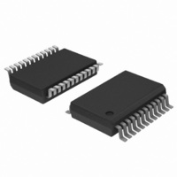
TDA9884TS/V1,112 NXP Semiconductors, TDA9884TS/V1,112 Datasheet - Page 3

TDA9884TS/V1,112
Manufacturer Part Number
TDA9884TS/V1,112
Description
IC IF-PLL I2C-BUS DEMOD 24-SSOP
Manufacturer
NXP Semiconductors
Type
Demodulatorr
Datasheet
1.TDA9884TSV1112.pdf
(58 pages)
Specifications of TDA9884TS/V1,112
Package / Case
*
Applications
Mobile Reception
Mounting Type
Surface Mount
Maximum Operating Temperature
+ 70 C
Minimum Operating Temperature
- 20 C
Mounting Style
SMD/SMT
Lead Free Status / RoHS Status
Lead free / RoHS Compliant
Other names
935270308112
TDA9884TS/V1
TDA9884TS/V1
TDA9884TS/V1
TDA9884TS/V1
Philips Semiconductors
Table 1.
[1]
[2]
[3]
[4]
[5]
[6]
[7]
TDA9884_2
Product data sheet
Symbol
AFC
Audio part
V
THD
B
S/N
PSRR
V
Reference frequency input (pin REF)
f
V
ref
AM(sup)
o(AF)(rms)
AF( 3dB)
o(intc)(rms)
ref(rms)
W(AF)
Values of video and sound parameters can be decreased at V
For applications without I
Condition: luminance range (5 steps) from 0 % to 100 %.
AC load: C
sound carrier traps (see
Measurement using unified weighting filter (“ ITU-T J.61” ), 200 kHz high-pass filter, 5 MHz low-pass filter and subcarrier notch filter
(“ ITU-T J.64” ).
The intercarrier output signal at pin SIOMAD can be calculated by the following formulae taking into account the internal video signal
with 1.1 V (p-p) as a reference:
the correction term for RMS value,
term of internal circuitry and 3 dB is the tolerance of video output and intercarrier output V
Pin REF is able to operate as a 1-pin crystal oscillator input as well as an external reference signal input, e.g. from the tuning system.
stps
Quick reference data
L
< 20 pF and R
Parameter
AFC control steepness
AF output voltage (RMS value)
total harmonic distortion
weighted signal-to-noise ratio of
audio signal
AM suppression of
FM demodulator
power supply ripple rejection
IF intercarrier output level
(RMS value)
reference signal frequency
reference signal voltage
(RMS value)
3 dB AF bandwidth
Figure 16
2
C-bus, the time constant (R
L
> 1 k . The sound carrier frequencies (depending on the TV standard) are attenuated by the integrated
V
o intc rms
…continued
to
--------------- - dB
V
V
Figure
i PC
i SC
21; H (s) is the absolute value of transfer function).
=
is the sound-to-picture carrier ratio at pins VIF1 and VIF2 in dB, 6 dB is the correction
1.1
Conditions
definition: I
27 kHz FM deviation;
50 s de-emphasis
FM: 27 kHz FM deviation;
50 s de-emphasis
AM: m = 54 %
without de-emphasis;
measured with FM-PLL
filter in
FM-PLL only:
27 kHz FM deviation;
50 s de-emphasis
AM: in accordance with
“ITU-R BS.468-4”
referenced to 27 kHz
FM deviation;
50 s de-emphasis;
AM: f = 1 kHz; m = 54 %
f
QSS mode; SC
L standard;
without modulation
intercarrier mode;
PC/SC
operation as input terminal
ripple
Rev. 02 — 12 May 2006
for FM
for AM
--------- -
2 2
C) at the supply must be > 1.2 s (e.g. 1
= 70 Hz; see
1
1
Figure 23
= 20 dB; SC
I
P
10
2
C-bus controlled multistandard alignment-free IF-PLL
= 4.5 V.
AFC
r
V
1
/ f
; SC
and
VIF
Figure 8
2
2
r
off
off
=
----- -
20
1
--------------- - dB
V
V
i SC
i PC
[6]
[7]
o(intc)(rms)
Min
0.85
430
-
-
80
52
45
40
90
90
-
-
14
20
80
© Koninklijke Philips Electronics N.V. 2006. All rights reserved.
and 2.2 F).
+
.
6 dB 3 dB
Typ
1.05
540
0.15
0.5
100
56
50
46
20
26
140
140
75
4
-
TDA9884
Max
1.25
650
0.50
1.0
-
-
-
-
-
-
180
180
-
-
400
, where:
Unit
mV
%
%
kHz
dB
dB
dB
dB
dB
mV
mV
mV
MHz
mV
A/kHz
--------- -
2 2
1
3 of 58
is


