DM163025 Microchip Technology, DM163025 Datasheet - Page 14
DM163025
Manufacturer Part Number
DM163025
Description
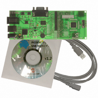
PIC DEM FULL SPEED USB DEMO BRD
Manufacturer
Microchip Technology
Specifications of DM163025
Main Purpose
Interface, USB 2.0 Host/Controller
Embedded
Yes, MCU, 8-Bit
Utilized Ic / Part
PIC18F2455/2550/4455/4550
Primary Attributes
Full Speed (12Mbps)
Secondary Attributes
MPLAB ICE 2000/4000 Emulator Interface, Temp Sensor, Expansion and PICtail Headers
Processor To Be Evaluated
PIC18F4550
Interface Type
RS-232, USB
Silicon Manufacturer
Microchip
Core Architecture
PIC
Core Sub-architecture
PIC18
Silicon Core Number
PIC18F
Silicon Family Name
PIC18F4xxx
Kit Contents
Demo Board, Cables, CD & Documents
Rohs Compliant
Yes
Lead Free Status / RoHS Status
Lead free / RoHS Compliant
Lead Free Status / RoHS Status
Lead free / RoHS Compliant, Lead free / RoHS Compliant
Other names
Q2086254
Available stocks
Company
Part Number
Manufacturer
Quantity
Price
Company:

Part Number:
DM163025
Manufacturer:
Microchip Technology
Quantity:
135
Company:
Part Number:
DM163025-1
Manufacturer:
MICROCHIP
Quantity:
12 000


DS51526B-page 10
™
1.4.1
The USB module of the PIC18F4550 requires a specific clock frequency input to oper-
ate correctly; specifically, 48 MHz is required when operating in Full-Speed mode, or
6 MHz when operating in Low-Speed mode. The PICDEM FS USB board uses a
20 MHz crystal oscillator as an external clock, and derives the necessary internal clock
frequencies from the 96 MHz PLL module. The clock configuration used on the
demonstration board is shown in Figure 1-2. A detailed explanation of how to set up the
clock configuration is explained in Chapter 2.0 of the PIC18F4550 device data sheet
(DS39632).
The PICDEM FS USB board is configured to run in Full-Speed USB mode, generating
an internal system clock of 48 MHz (equivalent to 12 MIPS) from the external 20 MHz
crystal.
FIGURE 1-2:
1.4.2
The PICDEM FS USB demonstration board operates at 5V. Power can be drawn
directly from the USB bus or from an external power supply. There are no jumpers to
select which power source to use. Instead, the power circuitry automatically selects the
external power source when both power sources are available. Two LEDs, D7 and D8,
are used to indicate the active power source. D7 indicates that the board is operating
in Bus Power mode; D8 indicates Self-Power mode (i.e., an external power supply).
Like most USB peripherals, the PICDEM FS USB board can be powered from the 5V
available from the USB cable. A minimum of 100 mA is always available on the bus for
a device; a maximum of 500 mA can be requested and used if available.
A barrel-type power supply connector (2.5 mm diameter) is also provided to run the
board from a 9-18 V
every example included will run from USB bus power.
Y1
Note:
Oscillator and Operating Frequency
Power
There are no power conditions that will cause both D7 and D8 to light at the
same time.
Oscillator
Primary
DC
PIC18F4550 CLOCK SETUP FOR PICDEM™ FS USB
20 MHz
power supply. A transformer is not supplied in the kit because
(requires 4 MHz
Input Prescaler
PIC18F4550 Oscillator Block
(configured as
Configurable
96 MHz PLL
divide-by-5)
Divide-by-2
input)
Fixed
4 MHz
96 MHz
96 MHz
Clock Postscaler
(configured as
Configurable
divide-by-2)
© 2008 Microchip Technology Inc.
48 MHz
48 MHz
USB
Clock
CPU and
Peripherals
Clock
Related parts for DM163025
Image
Part Number
Description
Manufacturer
Datasheet
Request
R

Part Number:
Description:
Manufacturer:
Microchip Technology Inc.
Datasheet:
Part Number:
Description:
Manufacturer:
Microchip Technology Inc.
Datasheet:
Part Number:
Description:
Manufacturer:
Microchip Technology Inc.
Datasheet:
Part Number:
Description:
Manufacturer:
Microchip Technology Inc.
Datasheet:
Part Number:
Description:
Manufacturer:
Microchip Technology Inc.
Datasheet:
Part Number:
Description:
Manufacturer:
Microchip Technology Inc.
Datasheet:
Part Number:
Description:
Manufacturer:
Microchip Technology Inc.
Datasheet:
Part Number:
Description:
Manufacturer:
Microchip Technology Inc.
Datasheet: