DM163025 Microchip Technology, DM163025 Datasheet - Page 35
DM163025
Manufacturer Part Number
DM163025
Description
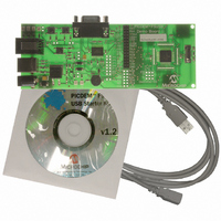
PIC DEM FULL SPEED USB DEMO BRD
Manufacturer
Microchip Technology
Specifications of DM163025
Main Purpose
Interface, USB 2.0 Host/Controller
Embedded
Yes, MCU, 8-Bit
Utilized Ic / Part
PIC18F2455/2550/4455/4550
Primary Attributes
Full Speed (12Mbps)
Secondary Attributes
MPLAB ICE 2000/4000 Emulator Interface, Temp Sensor, Expansion and PICtail Headers
Processor To Be Evaluated
PIC18F4550
Interface Type
RS-232, USB
Silicon Manufacturer
Microchip
Core Architecture
PIC
Core Sub-architecture
PIC18
Silicon Core Number
PIC18F
Silicon Family Name
PIC18F4xxx
Kit Contents
Demo Board, Cables, CD & Documents
Rohs Compliant
Yes
Lead Free Status / RoHS Status
Lead free / RoHS Compliant
Lead Free Status / RoHS Status
Lead free / RoHS Compliant, Lead free / RoHS Compliant
Other names
Q2086254
Available stocks
Company
Part Number
Manufacturer
Quantity
Price
Company:

Part Number:
DM163025
Manufacturer:
Microchip Technology
Quantity:
135
Company:
Part Number:
DM163025-1
Manufacturer:
MICROCHIP
Quantity:
12 000


5.1
5.2
© 2008 Microchip Technology Inc.
Chapter 5. Reconfiguring the PICDEM™ FS USB Hardware
HIGHLIGHTS
CONFIGURING THE DEMONSTRATION BOARD OPTIONS
This chapter covers the following:
• Configuring the Demonstration Board Options
• Restoring the PICDEM™ FS USB Firmware
The PICDEM FS USB board can be configured to enable or disable its various hard-
ware features. A total of 16 jumper locations are controlled in various places around the
board. As shipped from the factory, all of the locations are bridged by circuit traces and
all of the features are enabled. To change this, the user will need to cut the traces, and
install pins and a block jumper. Afterwards, the features can be enabled or disabled
easily by installing or removing the jumper.
In some instances, a single function (such as the digital temperature sensor) is
connected to the rest of the board through more than one jumper. This allows selective
tailoring of the controller’s I/O ports to any application that the user may develop.
Specific cases are discussed in the following sections.
The functions of the jumpers are listed in Table 5-1; their locations are shown in
Figure 5-1.
TABLE 5-1:
Number
10
11
12
13
14
1
2
3
4
5
6
7
8
9
Board ID(s)
JP14, JP15,
JP10
JP11
JP12
JP13
JP16
JP1
JP2
JP3
JP4
JP5
JP6
JP7
JP8
JP9
JUMPER DESCRIPTION
Bridge
Bridge
Bridge
Bridge
Bridge
Bridge
Bridge
Bridge
Bridge
Bridge
Bridge
Bridge
2-way
2-way
Type
Selects user-controlled Reset (S1) or microcontroller
disable for external emulation
Status LED bank (D1 through D4)
USART Receive (microcontroller’s perspective)
USART Flow Control (RTS)
USART Transmit (microcontroller’s perspective)
USART Flow Control (CTS)
S2 (user-defined switch 1)
S3 (user-defined switch 2)
R20 (potentiometer)
U4 (temperature sensor)
D7 (USB bus power LED)
ICD Port Configuration
PICDEM
USER’S GUIDE
Function
™
DS51526B-page 31
FS USB
Related parts for DM163025
Image
Part Number
Description
Manufacturer
Datasheet
Request
R

Part Number:
Description:
Manufacturer:
Microchip Technology Inc.
Datasheet:
Part Number:
Description:
Manufacturer:
Microchip Technology Inc.
Datasheet:
Part Number:
Description:
Manufacturer:
Microchip Technology Inc.
Datasheet:
Part Number:
Description:
Manufacturer:
Microchip Technology Inc.
Datasheet:
Part Number:
Description:
Manufacturer:
Microchip Technology Inc.
Datasheet:
Part Number:
Description:
Manufacturer:
Microchip Technology Inc.
Datasheet:
Part Number:
Description:
Manufacturer:
Microchip Technology Inc.
Datasheet:
Part Number:
Description:
Manufacturer:
Microchip Technology Inc.
Datasheet: