DM163025 Microchip Technology, DM163025 Datasheet - Page 15
DM163025
Manufacturer Part Number
DM163025
Description
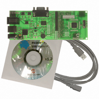
PIC DEM FULL SPEED USB DEMO BRD
Manufacturer
Microchip Technology
Specifications of DM163025
Main Purpose
Interface, USB 2.0 Host/Controller
Embedded
Yes, MCU, 8-Bit
Utilized Ic / Part
PIC18F2455/2550/4455/4550
Primary Attributes
Full Speed (12Mbps)
Secondary Attributes
MPLAB ICE 2000/4000 Emulator Interface, Temp Sensor, Expansion and PICtail Headers
Processor To Be Evaluated
PIC18F4550
Interface Type
RS-232, USB
Silicon Manufacturer
Microchip
Core Architecture
PIC
Core Sub-architecture
PIC18
Silicon Core Number
PIC18F
Silicon Family Name
PIC18F4xxx
Kit Contents
Demo Board, Cables, CD & Documents
Rohs Compliant
Yes
Lead Free Status / RoHS Status
Lead free / RoHS Compliant
Lead Free Status / RoHS Status
Lead free / RoHS Compliant, Lead free / RoHS Compliant
Other names
Q2086254
Available stocks
Company
Part Number
Manufacturer
Quantity
Price
Company:

Part Number:
DM163025
Manufacturer:
Microchip Technology
Quantity:
135
Company:
Part Number:
DM163025-1
Manufacturer:
MICROCHIP
Quantity:
12 000


© 2008 Microchip Technology Inc.
A USB host may send a query to a USB device to determine if it is currently
self-powered. Without an ability to sense the output of the 5V regulator (VR1), there
would be no way to determine the status of the power supply. The PICDEM FS USB
board uses two of the microcontroller’s I/O pins (PORTA<2:1>) to sense which supply
is available: PORTA<2> monitors the regulator, while PORTA<1> senses the USB
cable. When a port is read as ‘1’, its corresponding power source is active. When a port
is read as ‘0’, its source is disconnected. The combinations of PORTA states are shown
in Table 1-1.
For more details on power requirement and management, refer to Microchip applica-
tion note AN950, “Power Management for PIC18 USB Microcontrollers with nanoWatt
Technology” (DS00950).
TABLE 1-1:
1.4.3
The PICDEM FS USB board utilizes the on-chip USB voltage regulator, transceivers
and pull-up resistors of the PIC18F4550. This helps reduce the number of external
components. The USB connection can be electrically detached by disabling the USB
module in the firmware. By disabling the USB module in firmware (setting the USBEN
bit in the UCON register to ‘0’), the on-chip USB voltage regulator will also be disabled.
This simulates the physical detachment of the USB cable.
Figure 1-3 shows the electrical connection for the USB interface on the board.
FIGURE 1-3:
PORTA<1>
1
1
0
0
USB Connector
USB Interface
PORTA<2:1> STATE COMBINATIONS AND THEIR MEANINGS
1
2
3
4
PORTA<2>
USB INTERFACE, SHOWING ON-CHIP COMPONENTS
V
BUS
1
0
1
0
(5V)
USB cable and power supply are both connected; board is
self-powered, D8 is lit
USB cable is attached; board is bus-powered, D7 is lit
Power supply only is attached; board is self-powered, D8 is
lit
N/A
470 nF
RC4/D-
RC5/D+
(3.3V)
V
USB
1.5 kΩ
PIC18F4550 (partial)
1.5 kΩ
Status
Transceiver
USB 3.3V
Regulator
Voltage
USB
DS51526B-page 11
Related parts for DM163025
Image
Part Number
Description
Manufacturer
Datasheet
Request
R

Part Number:
Description:
Manufacturer:
Microchip Technology Inc.
Datasheet:
Part Number:
Description:
Manufacturer:
Microchip Technology Inc.
Datasheet:
Part Number:
Description:
Manufacturer:
Microchip Technology Inc.
Datasheet:
Part Number:
Description:
Manufacturer:
Microchip Technology Inc.
Datasheet:
Part Number:
Description:
Manufacturer:
Microchip Technology Inc.
Datasheet:
Part Number:
Description:
Manufacturer:
Microchip Technology Inc.
Datasheet:
Part Number:
Description:
Manufacturer:
Microchip Technology Inc.
Datasheet:
Part Number:
Description:
Manufacturer:
Microchip Technology Inc.
Datasheet: