DM163025 Microchip Technology, DM163025 Datasheet - Page 38
DM163025
Manufacturer Part Number
DM163025
Description
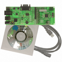
PIC DEM FULL SPEED USB DEMO BRD
Manufacturer
Microchip Technology
Specifications of DM163025
Main Purpose
Interface, USB 2.0 Host/Controller
Embedded
Yes, MCU, 8-Bit
Utilized Ic / Part
PIC18F2455/2550/4455/4550
Primary Attributes
Full Speed (12Mbps)
Secondary Attributes
MPLAB ICE 2000/4000 Emulator Interface, Temp Sensor, Expansion and PICtail Headers
Processor To Be Evaluated
PIC18F4550
Interface Type
RS-232, USB
Silicon Manufacturer
Microchip
Core Architecture
PIC
Core Sub-architecture
PIC18
Silicon Core Number
PIC18F
Silicon Family Name
PIC18F4xxx
Kit Contents
Demo Board, Cables, CD & Documents
Rohs Compliant
Yes
Lead Free Status / RoHS Status
Lead free / RoHS Compliant
Lead Free Status / RoHS Status
Lead free / RoHS Compliant, Lead free / RoHS Compliant
Other names
Q2086254
Available stocks
Company
Part Number
Manufacturer
Quantity
Price
Company:

Part Number:
DM163025
Manufacturer:
Microchip Technology
Quantity:
135
Company:
Part Number:
DM163025-1
Manufacturer:
MICROCHIP
Quantity:
12 000


5.3
DS51526B-page 34
RESTORING THE PICDEM FS USB FIRMWARE
™
5.2.4
In addition to the on-board PIC18F4550 microcontroller, the PICDEM FS USB demon-
stration board can also be configured to work with hardware emulators, such as the
MPLAB ICE 2000 and MPLAB ICE 4000. To do this, the user must install a 44-pin riser
in the area designated U5 on the board. This is comprised of four 11-pin pads arranged
in a square around the microcontroller. A device adapter (Microchip part number
DVA18PQ440) will also be required for either of the MPLAB ICE devices.
Before using an external emulator, users must also configure the board to disable the
existing controller. This is done by installing and configuring jumper, JP1. In its default
configuration, with the upper pins connected, JP1 assigns device Reset control to S1.
With the lower pins connected, JP1 grounds the MCLR pin of the PIC18F4550, holding
it in permanent Reset. In this state, any external controller or emulator connected to the
riser will control the demonstration board.
As shipped from the factory, the microcontroller on the PICDEM FS USB board is pre-
programmed with the firmware required to interact with the Demo Tool application. This
provides the code that makes the interactive Demo mode possible, and enables
communication to establish the Bootload mode.
As users develop their own USB applications, it is likely that the controller will be
reprogrammed with new firmware. If the original firmware is replaced, the status LEDs
and other interactive features of the board may no longer work as previously described.
It is even possible that USB connectivity may become disabled. For those users devel-
oping USB bootloader applications, it is possible that a change of device configuration
with firmware loaded through a bootloader may render the demonstration board
inoperable. In either case, it will be necessary to reprogram the board using an in-circuit
programmer, such as MPLAB ICD 2.
Should it ever become necessary to return the board to its original state, it will be
necessary to restore the original firmware. The necessary files have been installed on
the host PC with the rest of PICDEM FS USB software. In MCHPFSUSB v1.2, the
original hex file can be found in the directory, MCHPFSUSB\fw\_factory_hex\. The
exact location of this file may be different in other versions of the framework, so refer
to the MCHPFSUSB release notes if the file cannot be found. To reprogram the micro-
controller directly via the ICD connector with the original firmware, use the hex file,
picdemfsusb.hex.
Users should follow the procedure appropriate for their device programmer and
development environment.
Adding In-Circuit Emulation Capability
© 2008 Microchip Technology Inc.
Related parts for DM163025
Image
Part Number
Description
Manufacturer
Datasheet
Request
R

Part Number:
Description:
Manufacturer:
Microchip Technology Inc.
Datasheet:
Part Number:
Description:
Manufacturer:
Microchip Technology Inc.
Datasheet:
Part Number:
Description:
Manufacturer:
Microchip Technology Inc.
Datasheet:
Part Number:
Description:
Manufacturer:
Microchip Technology Inc.
Datasheet:
Part Number:
Description:
Manufacturer:
Microchip Technology Inc.
Datasheet:
Part Number:
Description:
Manufacturer:
Microchip Technology Inc.
Datasheet:
Part Number:
Description:
Manufacturer:
Microchip Technology Inc.
Datasheet:
Part Number:
Description:
Manufacturer:
Microchip Technology Inc.
Datasheet: