DM163025 Microchip Technology, DM163025 Datasheet - Page 25
DM163025
Manufacturer Part Number
DM163025
Description
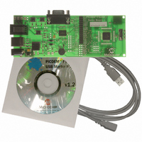
PIC DEM FULL SPEED USB DEMO BRD
Manufacturer
Microchip Technology
Specifications of DM163025
Main Purpose
Interface, USB 2.0 Host/Controller
Embedded
Yes, MCU, 8-Bit
Utilized Ic / Part
PIC18F2455/2550/4455/4550
Primary Attributes
Full Speed (12Mbps)
Secondary Attributes
MPLAB ICE 2000/4000 Emulator Interface, Temp Sensor, Expansion and PICtail Headers
Processor To Be Evaluated
PIC18F4550
Interface Type
RS-232, USB
Silicon Manufacturer
Microchip
Core Architecture
PIC
Core Sub-architecture
PIC18
Silicon Core Number
PIC18F
Silicon Family Name
PIC18F4xxx
Kit Contents
Demo Board, Cables, CD & Documents
Rohs Compliant
Yes
Lead Free Status / RoHS Status
Lead free / RoHS Compliant
Lead Free Status / RoHS Status
Lead free / RoHS Compliant, Lead free / RoHS Compliant
Other names
Q2086254
Available stocks
Company
Part Number
Manufacturer
Quantity
Price
Company:

Part Number:
DM163025
Manufacturer:
Microchip Technology
Quantity:
135
Company:
Part Number:
DM163025-1
Manufacturer:
MICROCHIP
Quantity:
12 000


3.4
© 2008 Microchip Technology Inc.
DEMO MODE
The Demo mode provides a simple interface between the board and the host system
to demonstrate USB connectivity. To start using the application, select “PICDEM FS
USB 0 (Demo)” from the “Select PICDEM FS USB Board” dropdown box. Click the
“Connect” button in the upper right hand corner. When the Demo Tool application suc-
cessfully connects to the board, the message “USB Demo Firmware Version x.x” will
appear on the left side of the status bar at the bottom of the window. There are three
interactive features in this mode.
Temperature Display
There are two temperature modes: Real Time and Data Logging. In Real-Time mode,
temperature data is streamed from the board to the PC continuously. Both the temper-
ature graph and the temperature value are updated periodically. All data is displayed in
centigrade unit with the graph display range of 16°C to 36°C. The easiest way to
change the temperature is to lightly blow air (warm or cold) on the sensor (U4).
In the Data Logging mode, temperature data is not sent to the host continuously.
Instead, temperature data is sampled every second and stored in the data memory
buffer until the “Acquire Data” button is clicked. At that point, the firmware sends every-
thing in the buffer to the PC, then empties the buffer. Data can be acquired at any time;
if the time elapsed since the last acquisition is less than 30 seconds, then a smaller set
of data points will be acquired and displayed in the message window. Clicking on
“Acquire Data” too rapidly may return a “WARNING-No Data Acquired” message; this
only means that the controller has not had an opportunity to collect a new temperature
sample. All data points are displayed at one time; the temperature graph is also
updated at that time. Clicking on “Clear Screen” clears the message window.
The firmware can store up to 30 data points; therefore, it takes 30 seconds to fill the
data memory buffer. When the buffer becomes full, the firmware replaces the oldest
data point with a newer data value.
FIGURE 3-3:
Toggle LEDs
The Toggle LEDs box contains two buttons used to control the status of LED D3 and
D4 on the demonstration board. The corresponding LED is turned on when a button is
pressed and off when the same button is pressed again.
Potentiometer Display
The Potentiometer Display reflects the current value of the potentiometer on the dem-
onstration board. The value ranges from 0 to 10 kΩ. Turning the potentiometer on the
board causes the analog dial gauge and digital display to change accordingly in real
time.
Ending Demo Mode
To stop the demonstration program, click “Disconnect” or exit the application. Clicking
on the Bootload Mode tab also terminates Demo mode.
MESSAGE WINDOW IN DATA LOGGING MODE
DS51526B-page 21
Related parts for DM163025
Image
Part Number
Description
Manufacturer
Datasheet
Request
R

Part Number:
Description:
Manufacturer:
Microchip Technology Inc.
Datasheet:
Part Number:
Description:
Manufacturer:
Microchip Technology Inc.
Datasheet:
Part Number:
Description:
Manufacturer:
Microchip Technology Inc.
Datasheet:
Part Number:
Description:
Manufacturer:
Microchip Technology Inc.
Datasheet:
Part Number:
Description:
Manufacturer:
Microchip Technology Inc.
Datasheet:
Part Number:
Description:
Manufacturer:
Microchip Technology Inc.
Datasheet:
Part Number:
Description:
Manufacturer:
Microchip Technology Inc.
Datasheet:
Part Number:
Description:
Manufacturer:
Microchip Technology Inc.
Datasheet: