DM163025 Microchip Technology, DM163025 Datasheet - Page 29
DM163025
Manufacturer Part Number
DM163025
Description
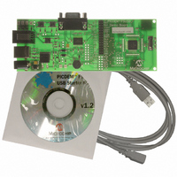
PIC DEM FULL SPEED USB DEMO BRD
Manufacturer
Microchip Technology
Specifications of DM163025
Main Purpose
Interface, USB 2.0 Host/Controller
Embedded
Yes, MCU, 8-Bit
Utilized Ic / Part
PIC18F2455/2550/4455/4550
Primary Attributes
Full Speed (12Mbps)
Secondary Attributes
MPLAB ICE 2000/4000 Emulator Interface, Temp Sensor, Expansion and PICtail Headers
Processor To Be Evaluated
PIC18F4550
Interface Type
RS-232, USB
Silicon Manufacturer
Microchip
Core Architecture
PIC
Core Sub-architecture
PIC18
Silicon Core Number
PIC18F
Silicon Family Name
PIC18F4xxx
Kit Contents
Demo Board, Cables, CD & Documents
Rohs Compliant
Yes
Lead Free Status / RoHS Status
Lead free / RoHS Compliant
Lead Free Status / RoHS Status
Lead free / RoHS Compliant, Lead free / RoHS Compliant
Other names
Q2086254
Available stocks
Company
Part Number
Manufacturer
Quantity
Price
Company:

Part Number:
DM163025
Manufacturer:
Microchip Technology
Quantity:
135
Company:
Part Number:
DM163025-1
Manufacturer:
MICROCHIP
Quantity:
12 000


© 2008 Microchip Technology Inc.
• Program Device: The program device function programs the target device with
• Abort Operation: The abort operation function is enabled when programming,
3.5.4
The PIC18F4550 microcontroller for the PICDEM FS USB board has a specific config-
uration setting that is necessary for the bootload program to function. The USB voltage
regulator and device oscillator settings are both critical and cannot be changed. Other
settings, such as code protection, WDT and LVP, are less critical, but may cause
irreversible side effects. The default configuration values are shown in Table 3-1.
The configuration data contained in a hex file may violate the restrictions on the critical
configuration settings described above. Should this happen, the Demo Tool will display
a warning dialog box (Figure 3-6). This will also be accompanied by a brief text descrip-
tion of the configuration conflict. Users have the option to accept the new configuration
settings, use the board’s factory configuration settings or maintain the current
configuration setting.
TABLE 3-1:
the data loaded in the memory buffer. Only the type of memory present in the
memory buffer will be programmed. The function automatically erases the pro-
gram memory (0x0800 to 0x7FFF) and user ID memory (0x200000 to 0x200007)
before writing new data to these locations. Memory contents are verified after the
write operation.
reading or erasing the device. This function causes the current operation to
terminate.
Note:
0x30000A
0x30000B
0x30000C
0x30000D
0x300000
0x300001
0x300002
0x300003
0x300005
0x300006
0x300008
0x300009
Address
Consideration When Using the Bootloader
Only implemented Configuration Words are listed.
DEFAULT CONFIGURATION WORD VALUES FOR THE
PICDEM™ FS USB BOARD
CONFIG1H
CONFIG2H
CONFIG3H
CONFIG5H
CONFIG6H
CONFIG7H
CONFIG1L
CONFIG2L
CONFIG4L
CONFIG5L
CONFIG6L
CONFIG7L
Register
Value
0x0E
0x1E
0xC0
0x24
0x3F
0x81
0x81
0x0F
0x0F
0xA0
0x0F
0x40
BOR, PWRT, USB voltage regulator
Core microcontroller configuration
Code-protect (program memory)
Table read-protect (program memory)
Clock configuration
Clock configuration
WDT configuration
MCLR, CCP2, A/D configuration
Code-protect (boot block/EEPROM)
Write-protect (program memory)
Write-protect (boot block/EEPROM)
Table read-protect (boot block/EEPROM)
Comment
DS51526B-page 25
Related parts for DM163025
Image
Part Number
Description
Manufacturer
Datasheet
Request
R

Part Number:
Description:
Manufacturer:
Microchip Technology Inc.
Datasheet:
Part Number:
Description:
Manufacturer:
Microchip Technology Inc.
Datasheet:
Part Number:
Description:
Manufacturer:
Microchip Technology Inc.
Datasheet:
Part Number:
Description:
Manufacturer:
Microchip Technology Inc.
Datasheet:
Part Number:
Description:
Manufacturer:
Microchip Technology Inc.
Datasheet:
Part Number:
Description:
Manufacturer:
Microchip Technology Inc.
Datasheet:
Part Number:
Description:
Manufacturer:
Microchip Technology Inc.
Datasheet:
Part Number:
Description:
Manufacturer:
Microchip Technology Inc.
Datasheet: