DM163025 Microchip Technology, DM163025 Datasheet - Page 30
DM163025
Manufacturer Part Number
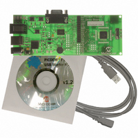
DM163025
Description
PIC DEM FULL SPEED USB DEMO BRD
Manufacturer
Microchip Technology
Specifications of DM163025
Main Purpose
Interface, USB 2.0 Host/Controller
Embedded
Yes, MCU, 8-Bit
Utilized Ic / Part
PIC18F2455/2550/4455/4550
Primary Attributes
Full Speed (12Mbps)
Secondary Attributes
MPLAB ICE 2000/4000 Emulator Interface, Temp Sensor, Expansion and PICtail Headers
Processor To Be Evaluated
PIC18F4550
Interface Type
RS-232, USB
Silicon Manufacturer
Microchip
Core Architecture
PIC
Core Sub-architecture
PIC18
Silicon Core Number
PIC18F
Silicon Family Name
PIC18F4xxx
Kit Contents
Demo Board, Cables, CD & Documents
Rohs Compliant
Yes
Lead Free Status / RoHS Status
Lead free / RoHS Compliant
Lead Free Status / RoHS Status
Lead free / RoHS Compliant, Lead free / RoHS Compliant
Other names
Q2086254
Available stocks
Company
Part Number
Manufacturer
Quantity
Price
Company:

Part Number:
DM163025
Manufacturer:
Microchip Technology
Quantity:
135
Company:
Part Number:
DM163025-1
Manufacturer:
MICROCHIP
Quantity:
12 000


DS51526B-page 26
™
FIGURE 3-6:
When a file is loaded, either from a device or a file, the bootloader demo software also
parses the file to determine if code is available for the different memory areas. If a
device is programmed with that file, only those memory areas with code present are
programmed; the other memory areas are left unchanged. For example, a hex file that
is missing data for the data EEPROM or Configuration Words will only program the
target device’s program memory and user ID spaces; the existing configuration and
stored EEPROM information will be preserved.
3.5.5
The bootloader operates as a separate entity, which means that an application can be
developed with very little concern about what the bootloader is doing. This is as it
should be; the bootloader should be dormant code until an event initiates its operation.
Ideally, bootloader code should never be running during an application’s intended
normal operation.
When developing an application with a resident bootloader, some basic principles must
be kept in mind:
3.5.5.1
When writing in assembly, the boot block and new vectors must be considered. For
modular code, this is usually just a matter of changing the linker script file for the
project. An example is shown in Example 3-1. If an absolute address is assigned to a
code section, the address must point somewhere above the boot block.
For those who write absolute assembly, all that is necessary is to remember that the
new Reset vector is at 800h, and the interrupt vectors are at 808h and 818h. Except for
the bootloader, no code should reside in the boot block area.
Writing Application Code with the Bootloader
WRITING IN ASSEMBLY
CONFIGURATION CONFLICT WARNING DIALOG WITH
TYPICAL DIAGNOSTIC MESSAGE
© 2008 Microchip Technology Inc.
Related parts for DM163025
Image
Part Number
Description
Manufacturer
Datasheet
Request
R

Part Number:
Description:
Manufacturer:
Microchip Technology Inc.
Datasheet:
Part Number:
Description:
Manufacturer:
Microchip Technology Inc.
Datasheet:
Part Number:
Description:
Manufacturer:
Microchip Technology Inc.
Datasheet:
Part Number:
Description:
Manufacturer:
Microchip Technology Inc.
Datasheet:
Part Number:
Description:
Manufacturer:
Microchip Technology Inc.
Datasheet:
Part Number:
Description:
Manufacturer:
Microchip Technology Inc.
Datasheet:
Part Number:
Description:
Manufacturer:
Microchip Technology Inc.
Datasheet:
Part Number:
Description:
Manufacturer:
Microchip Technology Inc.
Datasheet: