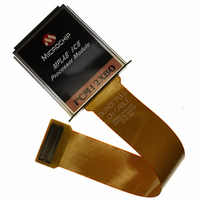
XE8000EV120 Semtech, XE8000EV120 Datasheet - Page 71

XE8000EV120
Manufacturer Part Number
XE8000EV120
Description
BOARD EVAL FOR SX8722I070TRLF
Manufacturer
Semtech
Series
ZoomingADC™r
Specifications of XE8000EV120
Number Of Adc's
1
Number Of Bits
16
Data Interface
I²C
Inputs Per Adc
7 Single or 4 Differential
Voltage Supply Source
Single Supply
Operating Temperature
-40°C ~ 125°C
Utilized Ic / Part
SX8722
Lead Free Status / RoHS Status
Lead free / RoHS Compliant
Other names
XM8000EV120
XM8000EV120
XM8000EV120
lower, no spikes will arise, but a small offset can be generated by the integration of the charges generated by the switched
capacitors, this corresponds to the mean impedance effect.
Note:
One can increase the mean input impedance of the ZoomingADC by lowering the acquisition clock fs.
One can increase the mean input impedance of the ZoomingADC by decreasing the gain of the first enabled amplifier.
One can increase the effective input impedance of the ZoomingADC by having a source with a high electrical bandwidth (sensor electrical
12.12. PGA Settling or Input Channel Modifications
PGAs are reset after each writing operation to registers CxZadcReg1-5. Similarly, input channels are switched after
modifications of AMUX[4:0] or VMUX. To ensure precise conversion, the ADC must be started after a PGA or inputs
common-mode stabilization delay. This is done by writing bit START several cycles after PGA settings modification or
channel switching. Delay between PGA start or input channel switching and ADC start should be equivalent to OSR
(between 8 and 1024) number of cycles. This delay does not apply to conversions made without the PGAs.
If the ADC is not settled within the specified period, there is most probably an input impedance problem (see previous
section).
12.13. PGA Gain & Offset, Linearity and Noise
Hereafter are a few design guidelines that should be taken into account when using the ZoomingADC :
1. Keep in mind that increasing the overall PGA gain, or "zooming" coefficient, improves linearity but degrades noise
performance.
2. Use the minimum number of PGA stages necessary to produce the desired gain ("zooming") and offset. Bypass
unnecessary PGAs.
3. Put most gain on PGA3 and use PGA2 and PGA1 only if necessary.
4. PGA3 should be always ON for best linearity.
5. For low-noise applications where power consumption is not a primary concern, maintain the largest bias currents in the
PGAs and in the ADC; i.e. set IB_AMP_PGA[1:0] = IB_AMP_ADC[1:0] = '11'.
6. For lowest output offset error at the output of the ADC, bypass PGA2 and PGA3. Indeed, PGA2 and PGA3 typically
introduce an offset of about 5 to 10 LSB (16 bit) at their output. Note, however, that the ADC output offset is easily calibrated
out by software.
12.14. Power Reduction
The ZoomingADC is particularly well suited for low-power applications. When very low power consumption is of primary
concern, such as in battery operated systems, several parameters can be used to reduce power consumption as follows:
1. Operate the acquisition chain with a reduced supply voltage V
2. Disable the PGAs which are not used during analog-to-digital conversion with ENABLE[3:0].
3. Disable all PGAs and the ADC when the system is idle and no
conversion is performed.
4. Use lower bias currents in the PGAs and the ADC using the
control words IB_AMP_PGA[1:0] and IB_AMP_ADC[1:0].
5. Reduce sampling frequency.
ACS - Revision 4.2
©2008 Semtech Corp.
ADVANCED COMMUNICATIONS & SENSING
bandwidth much higher than fs).
October 2008
Page 71
BATT
[
.
V
High gain acquisition for sensor interface
2
]
DATASHEET
www.semtech.com
SX8722


