AT32UC3B164-Z1UT Atmel, AT32UC3B164-Z1UT Datasheet - Page 43
AT32UC3B164-Z1UT
Manufacturer Part Number
AT32UC3B164-Z1UT
Description
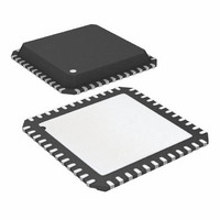
IC MCU AVR32 64KB FLASH 48-QFN
Manufacturer
Atmel
Series
AVR®32 UC3r
Specifications of AT32UC3B164-Z1UT
Core Processor
AVR
Core Size
32-Bit
Speed
60MHz
Connectivity
I²C, IrDA, SPI, SSC, UART/USART, USB
Peripherals
Brown-out Detect/Reset, DMA, POR, PWM, WDT
Number Of I /o
28
Program Memory Size
64KB (64K x 8)
Program Memory Type
FLASH
Ram Size
16K x 8
Voltage - Supply (vcc/vdd)
1.65 V ~ 1.95 V
Data Converters
A/D 6x10b
Oscillator Type
Internal
Operating Temperature
-40°C ~ 85°C
Package / Case
48-QFN Exposed Pad
Processor Series
AT32UC3x
Core
AVR32
Data Bus Width
32 bit
Data Ram Size
16 KB
Interface Type
2-Wire, SPI, USART
Maximum Clock Frequency
60 MHz
Number Of Programmable I/os
28
Number Of Timers
3
Maximum Operating Temperature
+ 85 C
Mounting Style
SMD/SMT
3rd Party Development Tools
EWAVR32, EWAVR32-BL
Development Tools By Supplier
ATAVRDRAGON, ATSTK500, ATSTK600, ATAVRISP2, ATAVRONEKIT, ATEXTWIFI, ATEVK1101
Minimum Operating Temperature
- 40 C
On-chip Adc
10 bit, 6 Channel
Package
48QFN EP
Device Core
AVR32
Family Name
AT32
Maximum Speed
60 MHz
Operating Supply Voltage
1.8|3.3 V
For Use With
ATSTK600-TQFP48 - STK600 SOCKET/ADAPTER 48-TQFPATAVRONEKIT - KIT AVR/AVR32 DEBUGGER/PROGRMMR770-1008 - ISP 4PORT ATMEL AVR32 MCU SPIATEVK1101 - KIT DEV/EVAL FOR AVR32 AT32UC3B
Lead Free Status / RoHS Status
Lead free / RoHS Compliant
Eeprom Size
-
Lead Free Status / Rohs Status
Details
Available stocks
Company
Part Number
Manufacturer
Quantity
Price

Part Number:
AT32UC3B164-Z1UT
Manufacturer:
ATMEL/爱特梅尔
Quantity:
20 000


9.5.7.3
9.5.7.4
9.5.8
32059K–03/2011
Generic clocks
Precautions when entering sleep mode
Wake Up
The power level of the internal voltage regulator is also adjusted according to the sleep mode to
reduce the internal regulator power consumption.
Modules communicating with external circuits should normally be disabled before entering a
sleep mode that will stop the module operation. This prevents erratic behavior when entering or
exiting sleep mode. Please refer to the relevant module documentation for recommended
actions.
Communication between the synchronous clock domains is disturbed when entering and exiting
sleep modes. This means that bus transactions are not allowed between clock domains affected
by the sleep mode. The system may hang if the bus clocks are stopped in the middle of a bus
transaction.
The CPU is automatically stopped in a safe state to ensure that all CPU bus operations are com-
plete when the sleep mode goes into effect. Thus, when entering Idle mode, no further action is
necessary.
When entering a sleep mode (except Idle mode), all HSB masters must be stopped before
entering the sleep mode. Also, if there is a chance that any PB write operations are incomplete,
the CPU should perform a read operation from any register on the PB bus before executing the
sleep instruction. This will stall the CPU while waiting for any pending PB operations to
complete.
When entering a sleep mode deeper or equal to DeepStop, the VBus asynchronous interrupt
should be disabled (USBCON.VBUSTE = 0).
The USB can be used to wake up the part from sleep modes through register AWEN of the
Power Manager.
Timers, communication modules, and other modules connected to external circuitry may require
specific clock frequencies to operate correctly. The Power Manager contains an implementation
defined number of generic clocks that can provide a wide range of accurate clock frequencies.
Each generic clock module runs from either Oscillator 0 or 1, or PLL0 or 1. The selected source
can optionally be divided by any even integer up to 512. Each clock can be independently
enabled and disabled, and is also automatically disabled along with peripheral clocks by the
Sleep Controller.
AT32UC3B
43
Related parts for AT32UC3B164-Z1UT
Image
Part Number
Description
Manufacturer
Datasheet
Request
R

Part Number:
Description:
DEV KIT FOR AVR/AVR32
Manufacturer:
Atmel
Datasheet:

Part Number:
Description:
INTERVAL AND WIPE/WASH WIPER CONTROL IC WITH DELAY
Manufacturer:
ATMEL Corporation
Datasheet:
Part Number:
Description:
Low-Voltage Voice-Switched IC for Hands-Free Operation
Manufacturer:
ATMEL Corporation
Datasheet:
Part Number:
Description:
MONOLITHIC INTEGRATED FEATUREPHONE CIRCUIT
Manufacturer:
ATMEL Corporation
Datasheet:
Part Number:
Description:
AM-FM Receiver IC U4255BM-M
Manufacturer:
ATMEL Corporation
Datasheet:
Part Number:
Description:
Monolithic Integrated Feature Phone Circuit
Manufacturer:
ATMEL Corporation
Datasheet:
Part Number:
Description:
Multistandard Video-IF and Quasi Parallel Sound Processing
Manufacturer:
ATMEL Corporation
Datasheet:
Part Number:
Description:
High-performance EE PLD
Manufacturer:
ATMEL Corporation
Datasheet:
Part Number:
Description:
8-bit Flash Microcontroller
Manufacturer:
ATMEL Corporation
Datasheet:
Part Number:
Description:
2-Wire Serial EEPROM
Manufacturer:
ATMEL Corporation
Datasheet: