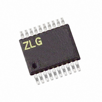
Z8F0411HH020SG Zilog, Z8F0411HH020SG Datasheet - Page 12

Z8F0411HH020SG
Manufacturer Part Number
Z8F0411HH020SG
Description
IC ENCORE MCU FLASH 4K 20SSOP
Manufacturer
Zilog
Series
Encore!® XP®r
Specifications of Z8F0411HH020SG
Core Processor
Z8
Core Size
8-Bit
Speed
20MHz
Connectivity
I²C, IrDA, UART/USART
Peripherals
Brown-out Detect/Reset, POR, PWM, WDT
Number Of I /o
11
Program Memory Size
4KB (4K x 8)
Program Memory Type
FLASH
Ram Size
1K x 8
Voltage - Supply (vcc/vdd)
2.7 V ~ 3.6 V
Oscillator Type
Internal
Operating Temperature
0°C ~ 70°C
Package / Case
20-SSOP
Controller Family/series
Z8
No. Of I/o's
11
Ram Memory Size
1KB
Cpu Speed
20MHz
No. Of Timers
2
Rohs Compliant
Yes
Processor Series
Z8F041xx
Core
eZ8
Data Bus Width
8 bit
Data Ram Size
1 KB
Interface Type
I2C, UART
Maximum Clock Frequency
20 MHz
Number Of Programmable I/os
11
Number Of Timers
2
Operating Supply Voltage
2.7 V to 3.6 V
Maximum Operating Temperature
+ 70 C
Mounting Style
SMD/SMT
Minimum Operating Temperature
0 C
For Use With
770-1002 - ISP 4PORT ZILOG Z8 ENCORE! MCU269-4643 - KIT DEV Z8 ENCORE XP 28-PIN269-4630 - DEV KIT FOR Z8 ENCORE 8K/4K269-4629 - KIT DEV Z8 ENCORE XP 28-PIN269-4628 - KIT DEV Z8 ENCORE XP 8-PIN
Lead Free Status / RoHS Status
Lead free / RoHS Compliant
Eeprom Size
-
Data Converters
-
Lead Free Status / Rohs Status
Details
Other names
269-4101
Z8F0411HH020SG
Z8F0411HH020SG
Available stocks
Company
Part Number
Manufacturer
Quantity
Price
Company:
Part Number:
Z8F0411HH020SG
Manufacturer:
Zilog
Quantity:
68
- Current page: 12 of 264
- Download datasheet (6Mb)
PS022517-0508
Safeguards
Caution:
Abbreviations/Acronyms
Use of All Uppercase Letters
The use of all uppercase letters designates the names of states, modes, and commands.
•
•
•
Bit Numbering
Bits are numbered from 0 to n–1 where n indicates the total number of bits. For example,
the 8 bits of a register are numbered from 0 to 7.
It is important that you understand the following safety terms, which are defined here.
This document uses the following abbreviations or acronyms.
Abbreviations/
Acronyms
ADC
LPO
SPI
WDT
GPIO
OCD
POR
LVD
VBO
ISR
UART
IrDA
I
2
C
Example 1: The bus is considered BUSY after the Start condition.
Example 2: A START command triggers the processing of the initialization
sequence.
Example 3: STOP mode.
directions.
Indicates a procedure or file can become corrupted if you does not follow
Expansion
Analog-to-Digital Converter
Low-Power Operational Amplifier
Serial Peripheral Interface
Watchdog Timer
General-Purpose Input/Output
On-Chip Debugger
Power-On Reset
Low-Voltage Detection
Voltage Brownout
Interrupt Service Routine
Universal Asynchronous Receiver/Transmitter
Infrared Data Association
Inter-Integrated Circuit
Z8 Encore! XP
Product Specification
®
F0822 Series
Introduction
xii
Related parts for Z8F0411HH020SG
Image
Part Number
Description
Manufacturer
Datasheet
Request
R

Part Number:
Description:
Communication Controllers, ZILOG INTELLIGENT PERIPHERAL CONTROLLER (ZIP)
Manufacturer:
Zilog, Inc.
Datasheet:

Part Number:
Description:
KIT DEV FOR Z8 ENCORE 16K TO 64K
Manufacturer:
Zilog
Datasheet:

Part Number:
Description:
KIT DEV Z8 ENCORE XP 28-PIN
Manufacturer:
Zilog
Datasheet:

Part Number:
Description:
DEV KIT FOR Z8 ENCORE 8K/4K
Manufacturer:
Zilog
Datasheet:

Part Number:
Description:
KIT DEV Z8 ENCORE XP 28-PIN
Manufacturer:
Zilog
Datasheet:

Part Number:
Description:
DEV KIT FOR Z8 ENCORE 4K TO 8K
Manufacturer:
Zilog
Datasheet:

Part Number:
Description:
CMOS Z8 microcontroller. ROM 16 Kbytes, RAM 256 bytes, speed 16 MHz, 32 lines I/O, 3.0V to 5.5V
Manufacturer:
Zilog, Inc.
Datasheet:

Part Number:
Description:
Low-cost microcontroller. 512 bytes ROM, 61 bytes RAM, 8 MHz
Manufacturer:
Zilog, Inc.
Datasheet:

Part Number:
Description:
Z8 4K OTP Microcontroller
Manufacturer:
Zilog, Inc.
Datasheet:

Part Number:
Description:
CMOS SUPER8 ROMLESS MCU
Manufacturer:
Zilog, Inc.
Datasheet:

Part Number:
Description:
SL1866 CMOSZ8 OTP Microcontroller
Manufacturer:
Zilog, Inc.
Datasheet:

Part Number:
Description:
SL1866 CMOSZ8 OTP Microcontroller
Manufacturer:
Zilog, Inc.
Datasheet:

Part Number:
Description:
OTP (KB) = 1, RAM = 125, Speed = 12, I/O = 14, 8-bit Timers = 2, Comm Interfaces Other Features = Por, LV Protect, Voltage = 4.5-5.5V
Manufacturer:
Zilog, Inc.
Datasheet:

Part Number:
Description:
Manufacturer:
Zilog, Inc.
Datasheet:


