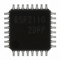
R5F21102DFP#U0 Renesas Electronics America, R5F21102DFP#U0 Datasheet - Page 146

R5F21102DFP#U0
Manufacturer Part Number
R5F21102DFP#U0
Description
IC R8C MCU FLASH 8K 32LQFP
Manufacturer
Renesas Electronics America
Series
M16C™ M16C/R8C/Tiny/10r
Datasheets
1.R5F211A2SPU0.pdf
(300 pages)
2.R5F21102FPU0.pdf
(30 pages)
3.R5F21102FPU0.pdf
(201 pages)
Specifications of R5F21102DFP#U0
Core Processor
R8C
Core Size
16-Bit
Speed
16MHz
Connectivity
SIO, UART/USART
Peripherals
LED, WDT
Number Of I /o
22
Program Memory Size
8KB (8K x 8)
Program Memory Type
FLASH
Ram Size
512 x 8
Voltage - Supply (vcc/vdd)
2.7 V ~ 5.5 V
Data Converters
A/D 8x10b
Oscillator Type
Internal
Operating Temperature
-40°C ~ 85°C
Package / Case
32-LQFP
For Use With
R0K521134S000BE - KIT EVAL STARTER FOR R8C/13R0E521134EPB00 - KIT EMULATOR PROBE FOR PC7501R0E521134CPE00 - EMULATOR COMPACT R8C/13
Lead Free Status / RoHS Status
Lead free / RoHS Compliant
Eeprom Size
-
Available stocks
Company
Part Number
Manufacturer
Quantity
Price
- Current page: 146 of 201
- Download datasheet (2Mb)
R8C/10 Group
Rev.1.20 Jan 27, 2006
REJ09B0019-0120
Timing requirements (Unless otherwise noted: V
NOTES:
Table 16.8 X
Table 16.10 TCIN input, INT3 input
Table 16.11 Serial Interface
1. When selecting the digital filter by the INT0 input filter select bit, use the INT0 input HIGH pulse width
Table 16.9 CNTR0 input, CNTR1 input, INT2 input
NOTES:
Table 16.12 External interrupt INT0 input
2. When selecting the digital filter by the INT0 input filter select bit, use the INT0 input LOW pusle width
1. When using the Timer C capture function, adjust the cycle time above ( 1/ Timer C count source
2. When using the Timer C capture function, adjust the pulse width above ( 1/ Timer C count source
t
t
t
t
t
t
t
t
t
t
t
t
t
t
t
t
t
t
C
WH
WL
C
WH
WL
W
W
C
W
W
d
h
su
h
C
WH
WL
Symbol
Symbol
Symbol
Symbol
Symbol
(
(
(
(
(
(
(X
to the greater value,either ( 1/ digital filter clock frequency x 3) or the minimum value of standard.
to the greater value,either ( 1/ digital filter clock frequency x 3) or the minimum value of standard.
(
(
(
(
C-Q
C-Q
C-D
(
CNTR0
TCIN
frequency x 3).
frequency x 1.5).
CK
INH
INL
CKH
CKL
(
(
D-C
(X
(
(
(X
CNTR0
TCIN
IN
CNTR0
TCIN
)
)
IN
)
)
)
IN
)
)
)
)
)
)
)
)
)
)
)
)
)
IN
X
X
X
CNTR0 input cycle time
CNTR0 input HIGH pulse width
CNTR0 input LOW pulse width
TCIN input cycle time
TCIN input HIGH pulse width
TCIN input LOW pulse width
INT0 input HIGH pulse width
INT0 input LOW pulse width
input
CLKi input cycle time
CLKi input HIGH pulse width
CLKi input LOW pulse width
TxDi output delay time
TxDi hold time
RxDi input setup time
RxDi input hold time
________
________
page 134 of 180
IN
IN
IN
input cycle time
input HIGH pulse width
input LOW pulse width
________
________
Parameter
Parameter
Parameter
Parameter
Parameter
________
________
________
CC
= 5V, V
SS
= 0V at Topr = 25 °C) [V
________
________
16. Electrical Characteristics
400
200
200
250
250
Min.
Min.
Min.
Min.
62.5
Min.
100
200
100
100
40
40
35
90
30
30
–
0
Standard
Standard
Standard
Standard
(1)
(2)
(2)
Standard
(1)
(2)
Max.
Max.
Max.
Max.
Max.
80
–
–
–
–
–
–
–
–
–
–
–
–
–
–
–
–
–
Unit
Unit
Unit
Unit
Unit
CC
ns
ns
ns
ns
ns
ns
ns
ns
ns
ns
ns
ns
ns
ns
ns
ns
ns
ns
=5V]
Related parts for R5F21102DFP#U0
Image
Part Number
Description
Manufacturer
Datasheet
Request
R

Part Number:
Description:
KIT STARTER FOR M16C/29
Manufacturer:
Renesas Electronics America
Datasheet:

Part Number:
Description:
KIT STARTER FOR R8C/2D
Manufacturer:
Renesas Electronics America
Datasheet:

Part Number:
Description:
R0K33062P STARTER KIT
Manufacturer:
Renesas Electronics America
Datasheet:

Part Number:
Description:
KIT STARTER FOR R8C/23 E8A
Manufacturer:
Renesas Electronics America
Datasheet:

Part Number:
Description:
KIT STARTER FOR R8C/25
Manufacturer:
Renesas Electronics America
Datasheet:

Part Number:
Description:
KIT STARTER H8S2456 SHARPE DSPLY
Manufacturer:
Renesas Electronics America
Datasheet:

Part Number:
Description:
KIT STARTER FOR R8C38C
Manufacturer:
Renesas Electronics America
Datasheet:

Part Number:
Description:
KIT STARTER FOR R8C35C
Manufacturer:
Renesas Electronics America
Datasheet:

Part Number:
Description:
KIT STARTER FOR R8CL3AC+LCD APPS
Manufacturer:
Renesas Electronics America
Datasheet:

Part Number:
Description:
KIT STARTER FOR RX610
Manufacturer:
Renesas Electronics America
Datasheet:

Part Number:
Description:
KIT STARTER FOR R32C/118
Manufacturer:
Renesas Electronics America
Datasheet:

Part Number:
Description:
KIT DEV RSK-R8C/26-29
Manufacturer:
Renesas Electronics America
Datasheet:

Part Number:
Description:
KIT STARTER FOR SH7124
Manufacturer:
Renesas Electronics America
Datasheet:

Part Number:
Description:
KIT STARTER FOR H8SX/1622
Manufacturer:
Renesas Electronics America
Datasheet:

Part Number:
Description:
KIT DEV FOR SH7203
Manufacturer:
Renesas Electronics America
Datasheet:


