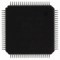
UPSD3422EV-40U6 STMicroelectronics, UPSD3422EV-40U6 Datasheet - Page 187

UPSD3422EV-40U6
Manufacturer Part Number
UPSD3422EV-40U6
Description
MCU 8BIT 8032 64KB FLASH 80TQFP
Manufacturer
STMicroelectronics
Series
µPSDr
Datasheet
1.UPSD3422EV-40U6.pdf
(300 pages)
Specifications of UPSD3422EV-40U6
Core Processor
8032
Core Size
8-Bit
Speed
40MHz
Connectivity
I²C, IrDA, SPI, UART/USART, USB
Peripherals
LVD, POR, PWM, WDT
Number Of I /o
46
Program Memory Size
80KB (80K x 8)
Program Memory Type
FLASH
Ram Size
4K x 8
Voltage - Supply (vcc/vdd)
3 V ~ 3.6 V
Data Converters
A/D 8x10b
Oscillator Type
Internal
Operating Temperature
-40°C ~ 85°C
Package / Case
80-TQFP, 80-VQFP
For Use With
497-5577 - BOARD EVAL USB POWER SWITCH497-5518 - EVAL BOARD RFID READER
Lead Free Status / RoHS Status
Lead free / RoHS Compliant
Eeprom Size
-
Other names
497-4905
Available stocks
Company
Part Number
Manufacturer
Quantity
Price
Company:
Part Number:
UPSD3422EV-40U6
Manufacturer:
STMicroelectronics
Quantity:
240
Company:
Part Number:
UPSD3422EV-40U6
Manufacturer:
STMicroelectronics
Quantity:
10 000
- Current page: 187 of 300
- Download datasheet (3Mb)
UPSD3422, UPSD3433, UPSD3434, UPSD3454
27.10
27.11
27.12
PWM mode - fixed frequency, 10-bit
The 10-bit PWM logic requires that all 3 TCMs in PCA0 or PCA1 operate in the same 10-bit
PWM mode. The 10-bit PWM operates in a similar manner as the 16-bit PWM, except the
PCACHm and PCACLm counters are reconfigured as 10-bit counters. The CAPCOMHn and
CAPCOMLn registers become 10-bit registers.
PWM duty cycle of each TCM module can be specified in the 10-bit CAPCOMHn and
CAPCOMLn registers. When the 10-bit PCA counter is equal or greater than the values in
the 10-bit registers CAPCOMHn and CAPCOMLn, the PWM output switches to a high state.
When the 10-bit PCA counter overflows, the PWM pin is switched to a logic low and starts
the next PWM pulse.
The most-significant 6 bits in the PCACHm counter and CAPCOMH register are “Don’t
cares” and have no effect on the PWM generation.
Writing to capture/compare registers
When writing a 16-bit value to the PCA Capture/Compare registers, the low byte should
always be written first. Writing to CAPCOMLn clears the E_COMP Bit to '0'; writing to
CAPCOMHn sets E_COMP to '1' the largest duty cycle is 100% (CAPCOMHn CAPCOMLn
= 0000h), and the smallest duty cycle is 0.0015% (CAPCOMHn CAPCOMLn = FFFFh). A
0% duty cycle may be generated by clearing the E_COMP Bit to ‘0’.
Control register bit definition
Each PCA has its own PCA_CONFIGn, and each module within the PCA block has its own
TCM_Mode register which defines the operation of that module (see
through
and PCA1 (see
Table 148. PCA0 control register PCACON0 (SFR 0A4h, reset value 00h)
Table 149. PCA0 register bit definition
EN-ALL
Bit 7
Bit
7
6
5
4
Table 150 on page
PCAIDLE
EN_PCA
EN_PCA
Symbol
EN-ALL
EOVFI
Bit 6
Table 152 on page
0 = No impact on TCM modules
1 = Enable both PCA counters simultaneously (override the EN_PCA Bits)
This bit is to start the two 16-bit counters in the PCA. For customers who
want 5 PWM, for example, this bit can start all of the PWM outputs.
0 = PCA counter is disabled
1 = PCA counter is enabled
EN_PCA Counter Run Control Bit. Set with software to turn the PCA
counter on. Must be cleared with software to turn the PCA counter off.
1 = Enable Counter Overflow Interrupt if overflow flag (OVF) is set
0 = PCA operates when CPU is in Idle Mode
1 = PCA stops running when CPU is in Idle Mode
EOVFI
Bit 5
188). There is one PCA_STATUS register that covers both PCA0
188).
PCAIDLE
Bit 4
Programmable counter array (PCA) with PWM
Bit 3
–
Function
Bit 2
–
Table 148 on page 187
Bit 1
CLK_SEL[1:0]
Bit 0
187/300
Related parts for UPSD3422EV-40U6
Image
Part Number
Description
Manufacturer
Datasheet
Request
R

Part Number:
Description:
Fast Turbo 8032 MCU with USB and Programmable Logic
Manufacturer:
STMICROELECTRONICS [STMicroelectronics]
Datasheet:

Part Number:
Description:
MCU 8BIT 8032 64KB FLASH 80TQFP
Manufacturer:
STMicroelectronics
Datasheet:

Part Number:
Description:
MCU 8BIT 8032 64KB FLASH 52TQFP
Manufacturer:
STMicroelectronics
Datasheet:

Part Number:
Description:
STMicroelectronics [RIPPLE-CARRY BINARY COUNTER/DIVIDERS]
Manufacturer:
STMicroelectronics
Datasheet:

Part Number:
Description:
STMicroelectronics [LIQUID-CRYSTAL DISPLAY DRIVERS]
Manufacturer:
STMicroelectronics
Datasheet:

Part Number:
Description:
BOARD EVAL FOR MEMS SENSORS
Manufacturer:
STMicroelectronics
Datasheet:

Part Number:
Description:
NPN TRANSISTOR POWER MODULE
Manufacturer:
STMicroelectronics
Datasheet:

Part Number:
Description:
TURBOSWITCH ULTRA-FAST HIGH VOLTAGE DIODE
Manufacturer:
STMicroelectronics
Datasheet:

Part Number:
Description:
Manufacturer:
STMicroelectronics
Datasheet:

Part Number:
Description:
DIODE / SCR MODULE
Manufacturer:
STMicroelectronics
Datasheet:

Part Number:
Description:
DIODE / SCR MODULE
Manufacturer:
STMicroelectronics
Datasheet:

Part Number:
Description:
Search -----> STE16N100
Manufacturer:
STMicroelectronics
Datasheet:


