DF2556FC20DV Renesas Electronics America, DF2556FC20DV Datasheet - Page 704
DF2556FC20DV
Manufacturer Part Number
DF2556FC20DV
Description
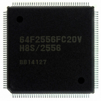
IC H8S/2556 MCU FLASH 144QFP
Manufacturer
Renesas Electronics America
Series
H8® H8S/2500r
Specifications of DF2556FC20DV
Core Processor
H8S/2000
Core Size
16-Bit
Speed
20MHz
Connectivity
CAN, I²C, SCI
Peripherals
POR, PWM, WDT
Number Of I /o
104
Program Memory Size
512KB (512K x 8)
Program Memory Type
FLASH
Ram Size
32K x 8
Voltage - Supply (vcc/vdd)
3 V ~ 5.5 V
Data Converters
A/D 16x10b; D/A 2x8b
Oscillator Type
Internal
Operating Temperature
-40°C ~ 85°C
Package / Case
144-QFP
Lead Free Status / RoHS Status
Lead free / RoHS Compliant
Eeprom Size
-
Available stocks
Company
Part Number
Manufacturer
Quantity
Price
Company:

Part Number:
DF2556FC20DV
Manufacturer:
Renesas Electronics America
Quantity:
135
Company:
Part Number:
DF2556FC20DV
Manufacturer:
Renesas Electronics America
Quantity:
10 000


Section 18 Controller Area Network (HCAN) [H8S/2556 Group]
18.7
A bus transceiver IC is necessary to connect this LSI to a CAN bus. A Philips PCA82C250
transceiver IC is recommended. Any other product must be compatible with the PCA82C250.
Figure 18.16 shows a sample connection diagram.
18.8
18.8.1
HCAN operation can be disabled or enabled using the module stop control register. The initial
setting is for HCAN operation to be halted. Register access is enabled by clearing module stop
mode. For details, see section 22, Power-Down Modes.
18.8.2
The HCAN is reset by a power-on reset or in hardware standby mode, software standby mode,
watch mode, or module stop mode. All the registers are initialized in a reset, however mailboxes
(message control (MCx[x])/message data (MDx[x])) are not. After power-on, mailboxes (message
control (MCx[x])/message data (MDx[x])) are initialized, and their values are undefined.
Therefore, mailbox initialization must always be carried out after a power-on reset or recovery
from hardware standby mode, software standby mode, watch mode, or module stop mode. The
reset interrupt flag (IRR0) is always set after a power-on reset or recovery from software standby
Rev. 6.00 Sep. 24, 2009 Page 656 of 928
REJ09B0099-0600
CAN Bus Interface
Usage Notes
Module Stop Mode Setting
Reset
Legend:
NC: No Connection
This LSI
Figure 18.16 High-Speed Interface Using PCA82C250
HRxD
HTxD
P1Vcc
NC
PCA82C250
RS
RxD
TxD
Vref
CANH
CANL
GND
Vcc
P1Vcc
124 Ω
124 Ω
CAN bus
Related parts for DF2556FC20DV
Image
Part Number
Description
Manufacturer
Datasheet
Request
R

Part Number:
Description:
KIT STARTER FOR M16C/29
Manufacturer:
Renesas Electronics America
Datasheet:

Part Number:
Description:
KIT STARTER FOR R8C/2D
Manufacturer:
Renesas Electronics America
Datasheet:

Part Number:
Description:
R0K33062P STARTER KIT
Manufacturer:
Renesas Electronics America
Datasheet:

Part Number:
Description:
KIT STARTER FOR R8C/23 E8A
Manufacturer:
Renesas Electronics America
Datasheet:

Part Number:
Description:
KIT STARTER FOR R8C/25
Manufacturer:
Renesas Electronics America
Datasheet:

Part Number:
Description:
KIT STARTER H8S2456 SHARPE DSPLY
Manufacturer:
Renesas Electronics America
Datasheet:

Part Number:
Description:
KIT STARTER FOR R8C38C
Manufacturer:
Renesas Electronics America
Datasheet:

Part Number:
Description:
KIT STARTER FOR R8C35C
Manufacturer:
Renesas Electronics America
Datasheet:

Part Number:
Description:
KIT STARTER FOR R8CL3AC+LCD APPS
Manufacturer:
Renesas Electronics America
Datasheet:
Part Number:
Description:
KIT STARTER FOR RX610
Manufacturer:
Renesas Electronics America
Datasheet:

Part Number:
Description:
KIT STARTER FOR R32C/118
Manufacturer:
Renesas Electronics America
Datasheet:

Part Number:
Description:
KIT DEV RSK-R8C/26-29
Manufacturer:
Renesas Electronics America
Datasheet:

Part Number:
Description:
KIT STARTER FOR SH7124
Manufacturer:
Renesas Electronics America
Datasheet:

Part Number:
Description:
KIT STARTER FOR H8SX/1622
Manufacturer:
Renesas Electronics America
Datasheet:

Part Number:
Description:
KIT DEV FOR SH7203
Manufacturer:
Renesas Electronics America
Datasheet: