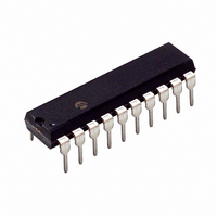
PIC16C770-I/P Microchip Technology, PIC16C770-I/P Datasheet - Page 3

PIC16C770-I/P
Manufacturer Part Number
PIC16C770-I/P
Description
IC MCU CMOS A/D 2K 20MHZ 20-DIP
Manufacturer
Microchip Technology
Series
PIC® 16Cr
Datasheets
1.PIC16C770-ISO.pdf
(220 pages)
2.PIC16C770-ISO.pdf
(6 pages)
3.PIC16C770-ISO.pdf
(8 pages)
Specifications of PIC16C770-I/P
Core Size
8-Bit
Program Memory Size
3.5KB (2K x 14)
Oscillator Type
Internal
Core Processor
PIC
Speed
20MHz
Connectivity
I²C, SPI
Peripherals
Brown-out Detect/Reset, POR, PWM, WDT
Number Of I /o
15
Program Memory Type
OTP
Ram Size
256 x 8
Voltage - Supply (vcc/vdd)
4 V ~ 5.5 V
Data Converters
A/D 6x12b
Operating Temperature
-40°C ~ 85°C
Package / Case
20-DIP (0.300", 7.62mm)
Controller Family/series
PIC16C
No. Of I/o's
16
Ram Memory Size
256Byte
Cpu Speed
20MHz
No. Of Timers
3
No. Of
RoHS Compliant
Core
PIC
Processor Series
PIC16C
Data Bus Width
8 bit
Maximum Clock Frequency
20 MHz
Data Ram Size
256 B
Data Rom Size
256 B
On-chip Adc
6 bit
Number Of Programmable I/os
16
Number Of Timers
3 bit
Operating Supply Voltage
2.5 V to 5.5 V
Mounting Style
Through Hole
Height
3.3 mm
Interface Type
I2C, SPI, SSP
Length
26.16 mm
Maximum Operating Temperature
+ 85 C
Minimum Operating Temperature
- 40 C
Supply Voltage (max)
5.5 V
Supply Voltage (min)
4 V
Width
6.35 mm
Lead Free Status / RoHS Status
Lead free / RoHS Compliant
For Use With
DVA16XP200 - ADAPTER ICE 20DIP/SOIC/SSOPAC164028 - MODULE SKT PROMATEII 20SOIC/DIP
Eeprom Size
-
Lead Free Status / Rohs Status
Details
Other names
PIC16C770I/P
Microcontroller Core Features:
• High-performance RISC CPU
• Only 35 single word instructions to learn
• All single cycle instructions except for program
• Operating speed: DC - 20 MHz clock input
• Interrupt capability (up to 10 internal/external
• Eight level deep hardware stack
• Direct, indirect and relative addressing modes
• Power-on Reset (POR)
• Power-up Timer (PWRT) and
• Watchdog Timer (WDT) with its own on-chip RC
• Selectable oscillator options:
• Low power, high speed CMOS EPROM
• In-Circuit Serial Programming™ (ICSP™
• Wide operating voltage range: 2.5V to 5.5V
• 15 I/O pins with individual control for:
• Commercial and Industrial temperature ranges
• Low power consumption:
M
Device
PIC16C717
PIC16C770
PIC16C771
18/20-Pin, 8-Bit CMOS Microcontrollers with 10/12-Bit A/D
branches which are two cycle
interrupt sources)
Oscillator Start-up Timer (OST)
oscillator for reliable operation
- INTRC - Internal RC, dual speed (4 MHz and
- ER - External resistor, dual speed (user
- EC - External clock
- HS - High speed crystal/resonator
- XT - Crystal/resonator
- LP - Low power crystal
technology
- Direction (15 pins)
- Digital/Analog input (6 pins)
- PORTB interrupt on change (8 pins)
- PORTB weak pull-up (8 pins)
- High voltage open drain (1 pin)
- < 2 mA @ 4V, 4 MHz
- 11 A typical @ 2.5V, 37 kHz
- < 1 A typical standby current
2002 Microchip Technology Inc.
37 kHz nominal) dynamically switchable for
power savings
selectable frequency and 37 kHz nominal)
dynamically switchable for power savings
Program
x14
2K
2K
4K
Memory
DC - 200 ns instruction cycle
Data
256 18, 20
256
256
x8
Pins
20
20
Resolution
10 bits
12 bits
12 bits
A/D
Channels
A/D
6
6
6
PIC16C717/770/771
Pin Diagram
Peripheral Features:
• Timer0: 8-bit timer/counter with 8-bit prescaler
• Timer1: 16-bit timer/counter with prescaler,
• Timer2: 8-bit timer/counter with 8-bit period
• Enhanced Capture, Compare, PWM (ECCP)
• Analog-to-Digital converter:
• On-chip absolute bandgap voltage reference
• Programmable Brown-out Reset (PBOR)
• Programmable Low-Voltage Detection (PLVD)
• Master Synchronous Serial Port (MSSP) with two
• Program Memory Read (PMR) capability for look-
RA2/AN2/V
RA3/AN3/V
can be incremented during SLEEP via external
crystal/clock
register, prescaler and postscaler
module
- Capture is 16-bit, max. resolution is 12.5 ns
- Compare is 16-bit, max. resolution is 200 ns
- PWM max. resolution is 10-bit
- Enhanced PWM:
- PIC16C770/771 12-bit resolution
- PIC16C717 10-bit resolution
generator
circuitry
circuitry
modes of operation:
- 3-wire SPI™ (supports all 4 SPI modes)
- I
up table, character string storage and checksum
calculation purposes
RA1/AN1/LVDIN
RA5/MCLR/V
- Single, Half-Bridge and Full-Bridge Output
- Digitally programmable deadband delay
support
2
C™ compatible including Master mode
RB0/AN4/INT
modes
RB1/AN5/SS
RA4/T0CKI
RA0/AN0
REF
REF
+/VRH
-/VRL
A
20-Pin PDIP, SOIC, SSOP
V
VSS
PP
SS
10
1
2
3
4
5
6
7
8
9
20
19
18
17
16
15
14
13
12
11
RB6/T1OSO/T1CKI/P1C
RB3/CCP1/P1A
RB2/SCK/SCL
RA7/OSC1/CLKIN
RA6/OSC2/CLKOUT
V
A
RB7/T1OSI/P1D
RB5/SDO/P1B
RB4/SDI/SDA
VDD
DD
DS41120B-page 1


